audi Workshop Repair Guides

Audi Workshop Service and Repair Manuals

Installing gearbox – vehicles with 1.8 ltr. and 2.0 ltr. TFSI engine > < Removing and installing gearbox
Removing gearbox – vehicles with 1.8 ltr. and 2.0 ltr. TFSI engine
   
Removing gearbox – vehicles with 1.8 ltr. and 2.0 ltr. TFSI engine
Special tools and workshop equipment required
t  Support bracket -10 - 222 A-
t  Ring spanner insert, 16 mm -V.A.G 1332/14-
t  Engine and gearbox jack -V.A.G 1383 A-
t  Stepladder -VAS 5085-
t  Puller -T40160-
t  Gearbox support -T40173-

   
t  Release tool -T40138-
  W00-10552
Removing
–  Bring wheels into straight-ahead position.
–  Switch off ignition and take out ignition key.
  Caution
When disconnecting the battery there is a risk of serious damage to electronic components:
Observe the correct procedure for disconnecting the battery → Rep. gr.27.
–  Disconnect battery → Rep. gr.27.
  A27-10141
–  Carefully detach engine cover panel from retaining studs in direction of -arrow-. Pull out engine cover panel evenly, without jerking.
  A10-10719
–  Set up support bracket -10 - 222 A- with -10 - 222 A /3- on suspension turrets (left and right), as shown in illustration.
–  Hook spindles -10 - 222 A /11- onto engine lifting eyes.
  A10-10993
–  Remove noise insulation panels -1- and -2- → Rep. gr.66.
  A10-11071
  Caution
Risk of damage to coil connector for airbag.
t  
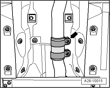
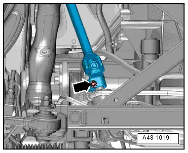
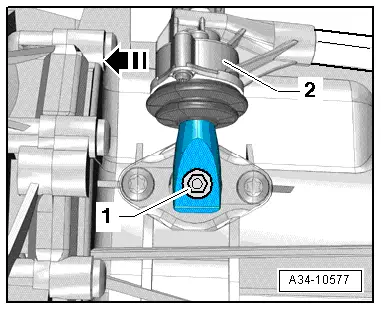
Front wheels must be in straight-ahead position when universal joint is detached from steering box.
t  Do not change position of steering wheel or steering box after this step (if necessary, fix steering wheel in position with adhesive tape).
–  Remove bolt -arrow- for universal joint → Rep. gr.48.
–  Press universal joint off steering box and push all the way up.
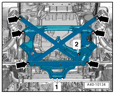
  Caution
Risk of damage to parts of the running gear.
Do NOT let the vehicle down on the wheels if the subframe, steering box or subframe cross brace are not properly installed.
Do NOT support the vehicle at the subframe or the subframe cross brace (e.g. with a trolley jack).
  A48-10191
A4 (all models), A5 Coupé:
–  Remove nut -1- for hydraulic line for power steering.
–  Remove bolts -arrows- and detach subframe cross brace.
  A10-10860
A5 Cabriolet:
–  Remove bolts -1- and -2- on left and right and detach brace.
  A40-10125
–  Remove bolt -2- for hydraulic fluid line for power steering.
–  Remove bolts -1- and -arrows- and detach subframe cross brace.
  A40-10134
Continued for all vehicles:
–  Engage 6th gear by pulling out selector shaft -1- and shifting gear selector lever -2- forwards in direction of -arrow-.
  A34-10577
–  Pull cover -1- off bottom of gearbox -arrow-.
  A10-10628
–  Remove 3 bolts -arrow- for drive plate (turn both front wheels so that crankshaft rotates 120° in direction of engine rotation each time).
  Note
  A10-10629
The flexible pipe connection (de-coupling element) in the front exhaust pipe must not be bent more than 10° - otherwise it can be damaged.
–  Disconnect exhaust system at clamp -arrow-.
–  Tie up front exhaust pipe to heat shield below selector mechanism with wire.
  A26-10015
–  Remove bolt -1- and swivel bracket for catalytic converter to right side.
  Note
Nuts -arrows- can be disregarded.
  A26-10352
–  Remove bolts -arrows- and detach heat shield for drive shaft (right-side).
  Note
The installation position is shown with the gearbox removed.
  A37-10841
–  Unbolt drive shafts (left and right) from flange shafts on gearbox.
  A40-10210
Vehicles with start/stop system:
–  Unplug electrical connector from gearbox neutral position sender -G701--1- and move wiring clear.
  A34-10804
Continued for all vehicles:
–  Remove bolt -2- and tie up clutch slave cylinder to side in engine compartment.
  Caution
Risk of damage to clutch slave cylinder.
Do not depress clutch pedal after removing slave cylinder.
–  Remove nut -1-.
  A10-10861
  Caution
Risk of damage to selector shaft in gearbox.
t  Do not prise off or knock off the gearbox selector lever -1- with a lever or hammer.
t  Always use puller -T40160- when removing the gearbox selector lever.
–  Apply puller -T40160- and pull off gearbox selector lever.
  A10-10862
–  Remove engine/gearbox securing bolts -8 … 11-.
  A34-10491
–  Position engine and gearbox jack -V.A.G 1383 A- with gearbox support -T40173- underneath gearbox and secure with tensioning strap -1- as shown in illustration.
  A37-10849
–  Remove bolts -arrows- for tunnel cross member.
  A10-10866
–  Lower gearbox initially only by dimension -a- using engine and gearbox jack -V.A.G 1383 A-.
l  Dimension -a- = 80 mm (maximum)
–  Pre-tension threaded spindles on support bracket -10 - 222 A- slightly.
  Note
Use stepladder -VAS 5085- for access to threaded spindles while vehicle is raised.
  A10-10867
–  Disconnect electrical connector -1- for gear detector switch -F208- using release tool -T40138- and move electrical wiring clear.
–  Remove bolt -2- for push rod.
–  Remove bolt -3- for connecting rod.
  A34-10492
–  Remove bolt -3- for starter from engine side.
–  Remove bolt -1-.
–  Detach spacer sleeve -2- between starter and gearbox.
–  Detach starter from gearbox but do not remove starter.
  Note
Starter cables do not have to be disconnected.
–  Remove remaining bolts securing engine to gearbox.
–  Detach gearbox from engine and lower carefully using engine and gearbox jack -V.A.G 1383 A-.
  A34-11082
–  If the removed gearbox is being replaced, the following components must be transferred to the replacement gearbox:
t  Bracket -1- for exhaust system mounting → Rep. gr.26.
t  Tunnel cross member, gearbox mounting and gearbox support → Chapter.
  A34-10503
t  Remove clutch module if necessary → Servicing 6-speed manual gearbox 0B1, front-wheel drive; Rep. gr.30.
  A30-10169

Installing gearbox – vehicles with 1.8 ltr. and 2.0 ltr. TFSI engine > < Removing and installing gearbox