
A4 Mk3
| Removing and installing selector lever cable |

| Special tools and workshop equipment required |
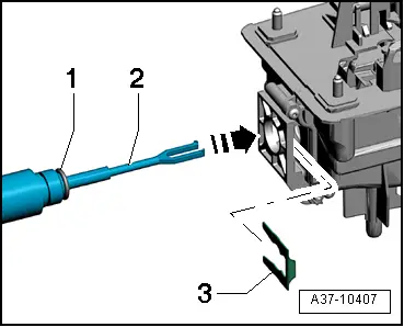
| t | Removal lever -80 - 200- |
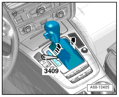
| t | Removal wedge -3409- |
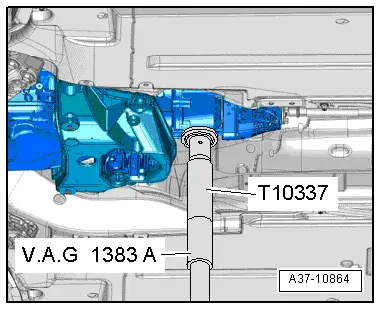
| t | Engine and gearbox jack -V.A.G 1383 A- |
| t | Gearbox support -T10337- |
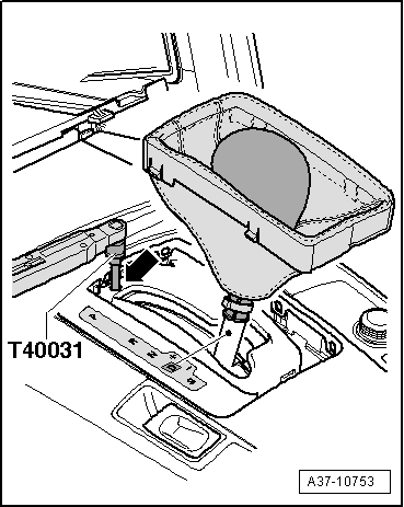
| t | Socket and key -T40031- |
|
|
 Note
Note
|
|
|
|
|
|
Note
|
|
 Caution
|
|
 WARNING
|
|
|
|
|
|
|
|
Note
|
|
Note
|
|
|
|
|
|
Note
|
|
Note
Note
|
|