
A4 Mk3
| Exploded view - servicing gearbox cover |

| Special tools and workshop equipment required |
| t | Drift -VW 207 C- |
| t | Thrust plate -VW 402- |
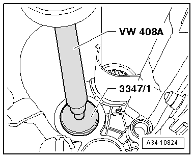
| t | Press tool -VW 408 A- |
| t | Press tool -VW 411- |
| t | Press tool -VW 412- |
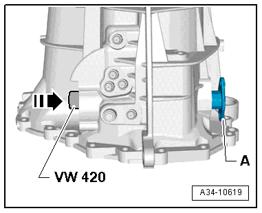
| t | Tube -VW 420- |

| t | Tube -VW 423- |
| t | Press tool -VW 434- |
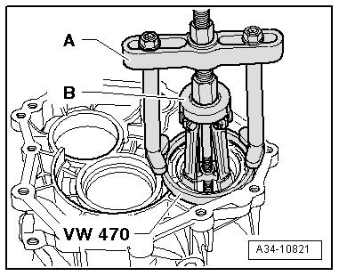
| t | Thrust pieces for drive pinion bearing -VW 470- |
| t | Sleeve -VW 472/2- |
| t | Guide pin -10 - 15- |
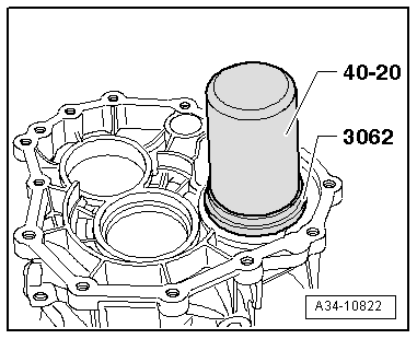
| t | Press tool -40 - 20- |

| t | Thrust plate -3005- |
| t | Thrust pad -3062- |
| t | Extension -3161- |
| t | Assembly tool -3347- |
| t | Shock absorber set -T10001- |
| t | Extractor hook -T20143- |
|
|
|
|
|
|

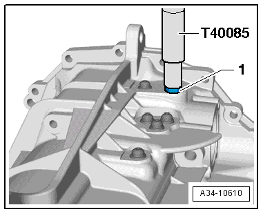
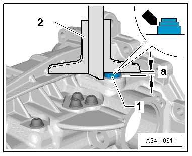
| 1 - | Large locking bush |
| q | For selector shaft |
| q | Removing and installing → Fig. |
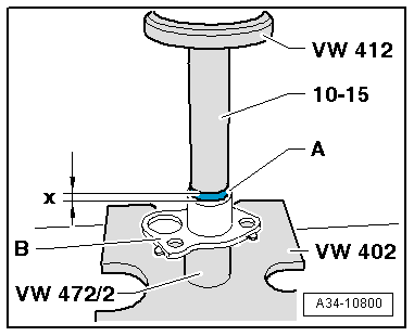
| q | Installation depth → Fig. |
| 2 - | Locking bush |
| q | For selector plate / selector fork |
| q | At present there is no provision for removing and installing |
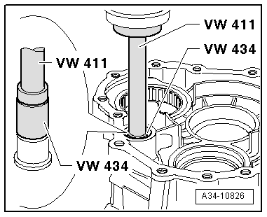
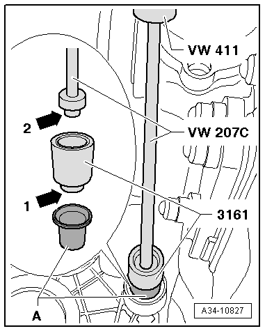
| 3 - | Needle bearing |
| q | For mounting output gear/spur gear mechanism |
| q | Extracting → Fig. |
| q | Always renew |
| q | Driving in → Fig. |
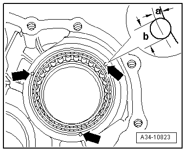
| q | Peen to secure after installing → Fig. |
| 4 - | Outer race/tapered roller bearing |
| q | For mounting input gear/spur gear mechanism in gearbox cover |
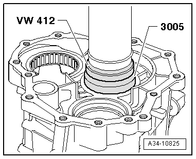
| q | Pressing out → Fig. |
| q | Pressing in → Fig. |
| 5 - | Gearbox cover |
| q | Select correct version according to gearbox code letters → Electronic parts catalogue |
| 6 - | Oil filler plug |
| q | 40 Nm |
| 7 - | O-ring |
| q | Only installed in gearboxes with sealing cap/selector shaft in conjunction with gearbox neutral position sender -G701- or sealing plug |
| q | Always renew |
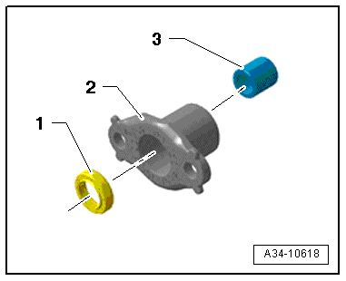
| 8 - | Sealing cap |
| q | For selector shaft in conjunction with gearbox neutral position sender -G701- or sealing plug |
| q | Not fitted on all versions |
| q | Select correct version according to gearbox code letters → Electronic parts catalogue |
| q | Exploded view → Fig. |
| q | Removing and installing oil seal for selector shaft → Fig. |
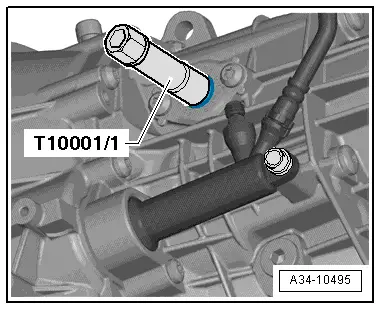
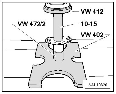
| q | Removing ball sleeve for selector shaft → Fig. |
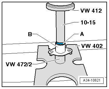
| q | Installing ball sleeve for selector shaft → Fig. |
| 9 - | Sealing plug |
| q | Not fitted on all versions |
| q | Select correct version according to gearbox code letters → Electronic parts catalogue |
| q | Renew O-ring on sealing plug; select correct version according to gearbox code letters → Electronic parts catalogue |
| 10 - | Bolt |
| q | 24 Nm |
| q | Steel bolts (M8; 25 mm long) |
| q | Apply locking fluid -AMV 185 101 A1- when fitting |
| 11 - | Gearbox neutral position sender -G701- |
| q | Not fitted on all versions |
| q | Select correct version according to gearbox code letters → Electronic parts catalogue |
| q | Renew O-ring on gearbox neutral position sender -G701-; select correct version according to gearbox code letters → Electronic parts catalogue |
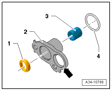
| 12 - | Sealing cap |
| q | For selector shaft without gearbox neutral position sender -G701- or sealing plug |
| q | Not fitted on all versions |
| q | Select correct version according to gearbox code letters → Electronic parts catalogue |
| q | Removing and installing → Fig. |
| q | Exploded view → Fig. |
| q | Removing and installing oil seal for selector shaft → Fig. |
| q | Removing ball sleeve for selector shaft → Fig. |
| q | Installing ball sleeve for selector shaft → Fig. |
| 13 - | Bearing bush |
| q | For 3rd/4th gear selector plate / selector fork |
| q | Pressing out → Fig. |
| q | Pressing in → Fig. |
| 14 - | Small locking bush |
| q | For selector shaft |
| q | At present there is no provision for removing and installing |
| 15 - | Breather pipe |
| q | Installation dimension: 17.5 mm ± 0.5 mm from upper edge of pipe on housing |
| q | Clip in cap for gearbox breather |
| 16 - | Cap |
| q | For gearbox breather |
|
|
|
|
|
|
 Note
Note
|
|
|
|
|
|
|
|
|
|
|
|
|
|
|
|
|
|
|
|
|
|
|
|