
A4 Mk3
| Assembly sequence - removing and installing selector fork cluster, input shaft, 1st, 2nd and reverse gears on output shaft |

| Special tools and workshop equipment required |
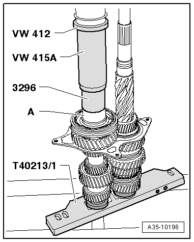
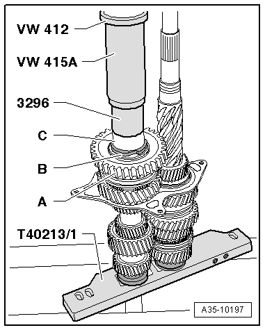
| t | Press tool -VW 412- |
| t | Tube -VW 415 A- |
| t | Thrust plate -VW 447 H- |
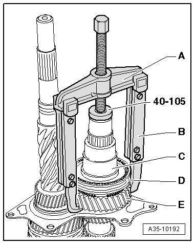
| t | Thrust plate -40 - 105- |
| t | Tube -3296- |
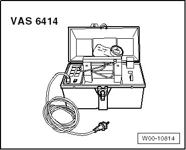
| t | Workshop press -V.A.G 1290A- |
|
|
|
|
|
|
|
|
|
|
 Note
Note
|
|
|
|
|
|
|
|
 Caution
|
|
Note
|
|
|
|
Note
|

|
|
|
|
|
|
|
|
|