audi Workshop Repair Guides

Audi Workshop Service and Repair Manuals

Cylinder head > < Toothed belt drive - exploded view
Removing and installing toothed belt
   
Removing and installing toothed belt
Special tools and workshop equipment required
t  2x Diesel injection pump locking pin -3359-
t  Crankshaft stop -T10050-
t  Counterhold tool -T10172-
t  Special wrench, long reach -T10264-
t  Locking tool -T10265-
t  Bit XZN 10 -T10385-

   
Removing
–  Remove engine cover panel -arrows-.
  A10-11353
–  Open clips -arrows- and remove toothed belt cover.
–  Remove vibration damper → Chapter.
  A10-11056
–  Remove bolts -arrows-.
–  Detach toothed belt cover (bottom).
  N13-10350
  Caution
Irreparable damage can be caused if the toothed belt slips.
Turn crankshaft only in direction of engine rotation.
–  Rotate crankshaft by turning bolt on crankshaft sprocket until camshaft sprocket is positioned at „TDC“.
–  Lock camshaft hub with diesel injection pump locking pin -3359-.
  Note
Disregard -arrows-.
  A15-10798
–  Lock crankshaft sprocket in position with crankshaft stop -T10050-.
l  The markings on the sprocket -2- and the crankshaft stop -1- must align -arrow-. The pin of the crankshaft stop must engage in the aperture in the sealing flange.
  Note
The crankshaft stop can only be pushed onto the sprocket from the front face of the teeth.
  A13-0350
–  Slacken bolts -arrows- for camshaft sprocket approx. 90°.
  A15-10798
–  Using bit XZN 10 -T10385-, loosen bolts -arrows- for toothed belt sprocket on high-pressure pump by approx. 90°.
  A15-11049
–  Loosen nut -1- for tensioning roller.
–  Turn eccentric adjuster of tensioning roller with special wrench, long reach -T10264- anti-clockwise -arrow- until tensioning roller can be secured with locking tool -T10265-.
  N15-10332
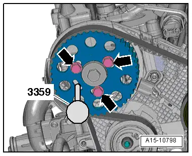
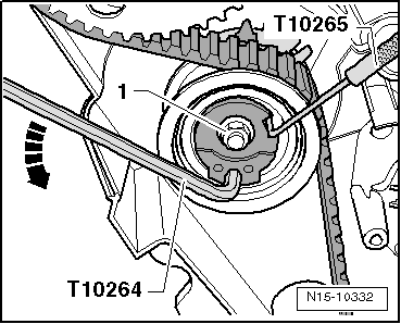
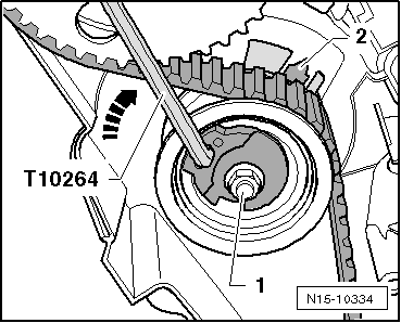
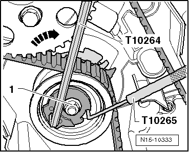
–  Then use special wrench, long reach -T10264- to turn eccentric adjuster of tensioning roller clockwise -arrow- as far as stop and tighten nut -1- by hand.
  Caution
If a used belt runs in the opposite direction when it is refitted, this can cause breakage.
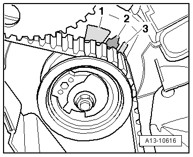
Before removing, mark direction of rotation of toothed belt with chalk or felt-tip pen for re-installation.
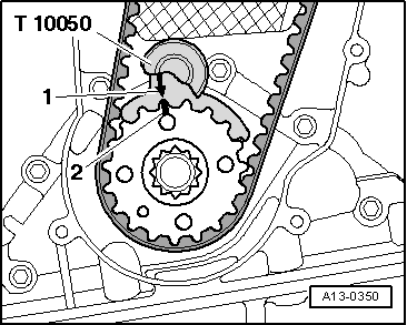
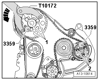
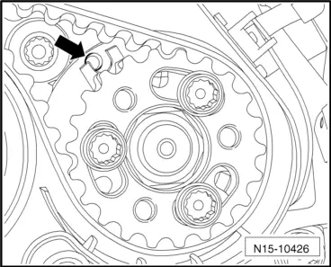
–  Take off toothed belt first from idler roller and then from remaining sprockets.
Installing (adjusting valve timing)
l  Tightening torques → Chapter „Toothed belt drive - exploded view“
  Note
Perform adjustments on toothed belt only when engine is cold.
  Caution
Avoid damage to valves and piston crowns.
The crankshaft must not be at „TDC“ at any cylinder when the camshaft is turned.
  N15-10333
Requirements:
l  Tensioning roller is locked with locking tool -T10265- and secured at right stop with nut -1-.
  N15-10333
l  Camshaft hub locked with diesel injection pump locking pin -3359-.
l  Bolts -arrows- are fitted but not tightened.
l  It should just be possible to turn the sprocket on the camshaft without axial movement.
  A15-10798
l  Crankshaft is locked in position with crankshaft stop -T10050-.
  A13-0350
l  Hub of high-pressure pump locked with diesel injection pump locking pin -3359-.
l  Bolts -1- are fitted but not tightened.
l  The high-pressure pump sprocket should still just turn, but there must be no axial movement.
  Note
  A13-10615
If necessary, apply a screwdriver -arrows- to bolt heads -1- and turn the high-pressure pump hub until it can be locked with the locking pin.
  N15-10427
–  Turn the camshaft sprocket and high-pressure pump sprocket in their elongated holes clockwise as far as the stop.
–  Install toothed belt in the specified sequence:
1 - Crankshaft sprocket
2 - Tensioning roller
3 - Camshaft sprocket
4 - Coolant pump sprocket
5 - High-pressure pump sprocket
6 - Idler roller
  A13-10540
–  Loosen nut -1- for tensioning roller and detach locking tool -T10265-.
  Note
Disregard -arrow-.
  Note
  N15-10333
Ensure that tensioning roller is seated properly in toothed belt cover (rear) -arrow-.
  N15-10424
–  Position counterhold tool -T10172- on camshaft sprocket as shown in illustration.
–  Apply force to counterhold tool in anti-clockwise direction -arrow- and maintain tension.
–  Tighten bolts -1- for camshaft sprocket and bolts -2- for high-pressure pump sprocket in this position.
l  Tightening torque: 20 Nm.
  A13-10614
–  Carefully turn eccentric adjuster of tensioning roller clockwise -arrow- using special wrench, long reach -T10264- until pointer -2- aligns with the centre of the slot on the base plate.
l  Nut -1- must not turn.
–  Hold tensioning roller in this position and tighten nut.
–  Remove locking pins -3359- and crankshaft stop -T10050-.
Checking valve timing:
  Caution
Irreparable damage can be caused if the toothed belt slips.
Turn crankshaft only in direction of engine rotation.
–  Turn crankshaft two rotations in direction of engine rotation by turning bolt for crankshaft sprocket until crankshaft is just before „TDC“.
  N15-10334
–  Fit crankshaft stop -T10050- to crankshaft sprocket again.
–  Then turn the crankshaft in direction of engine rotation until the pin -arrow- on the crankshaft stop engages in the sealing flange as the crankshaft rotates.
  N15-0446
l  It should now be possible to lock camshaft hub with diesel injection pump locking pin -3359-.
  Note
Disregard -arrows-.
  A15-10798
l  It is very difficult to reproduce the locking position of the high-pressure pump hub. However, a slight deviation -arrow- does not influence engine operation.
  N15-10426
l  Pointer -2- on tensioner roller must be centred between tabs -1- and -3- on base plate.
  Note
The maximum permissible sideways deviation from the specified position is 5 mm.
t  Re-adjust valve timing if requirements are not met → Anchor.
t  If requirements are met, continue with procedure after adjusting valve timing correctly as described below → Anchor.
Re-adjusting valve timing:
–  If camshaft hub cannot be locked, withdraw crankshaft stop -T10050- until pin is clear of bore.
–  Turn crankshaft in opposite direction of engine rotation slightly past „TDC“.
–  Now turn crankshaft slowly in direction of engine rotation until it is possible to lock camshaft hub.
–  Loosen bolts for camshaft sprocket after locking hub.
  A13-10616
A - If pin of crankshaft stop -T10050- is on left side of bore:
–  Then turn the crankshaft in direction of engine rotation until the pin -arrow- on the crankshaft stop engages in the sealing flange as the crankshaft rotates.
–  Tighten camshaft sprocket bolts to 20 Nm.
B - If pin of crankshaft stop -T10050- is on right side of bore:
–  Turn crankshaft slightly in opposite direction to engine rotation.
–  Turn crankshaft in direction of engine rotation again until pin of crankshaft stop engages in sealing flange as crankshaft rotates.
–  Tighten camshaft sprocket bolts to 20 Nm.
Procedure after adjusting valve timing correctly:
–  Remove diesel injection pump locking pin -3359- and crankshaft stop -T10050-.
–  Turn crankshaft two rotations in direction of engine rotation by turning bolt for crankshaft sprocket until crankshaft is just before „TDC“.
–  Check valve timing once again → Anchor.
  N15-0446
–  If camshaft hub can now be locked, tighten camshaft sprocket bolts -1- to final torque → Item.
–  Tighten bolts -2- for high-pressure pump sprocket to final torque → Rep. gr.23.
–  Check valve timing once again → Anchor.
Assembling
Installation is carried out in the reverse order; note the following:
  Note
t  Renew seals and/or gaskets.
t  Secure all hose connections with the correct type of hose clips (same as original equipment) → Electronic parts catalogue.
–  Install vibration damper → Chapter.
  A13-10614

Cylinder head > < Toothed belt drive - exploded view