audi Workshop Repair Guides

Audi Workshop Service and Repair Manuals

Removing and installing cylinder heads > < Removing and installing cylinder head cover (left-side)
Removing and installing cylinder head cover (right-side)
Special tools and workshop equipment required
   
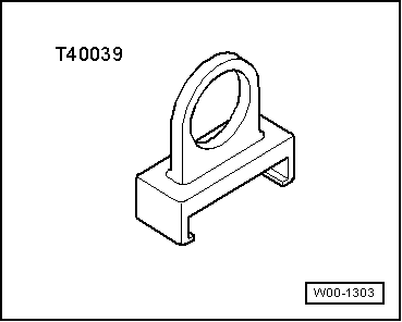
t  Puller -T40039-
  W00-1303
Removing
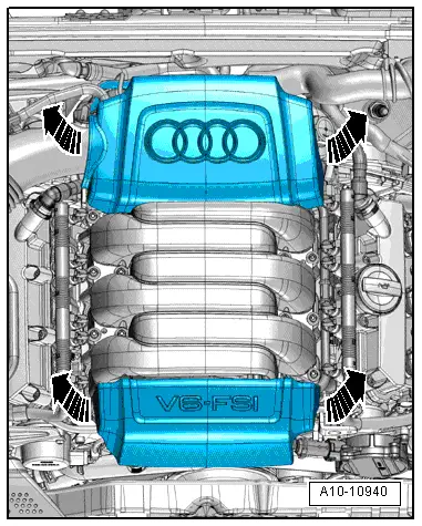
–  Pull off engine cover panels -arrows-.
  A10-10940
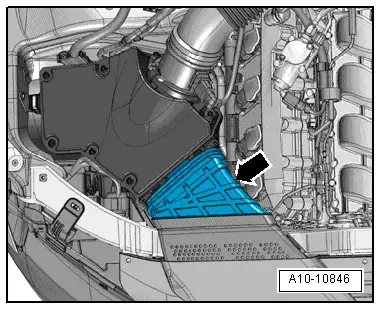
–  Remove air duct -arrow-.
  A10-10846
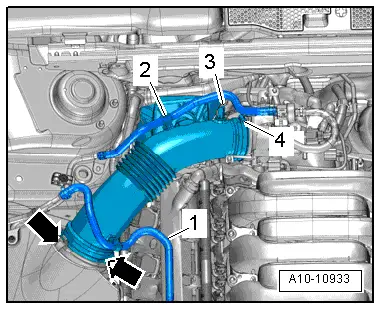
–  Move fuel line -1- and line -2- (leading to activated charcoal filter) clear at air pipe.
–  Disconnect vacuum hose -3- from connection on air pipe.
–  Remove air pipe. To do so, release hose clip -4- and clamps -arrows-.
  A10-10933
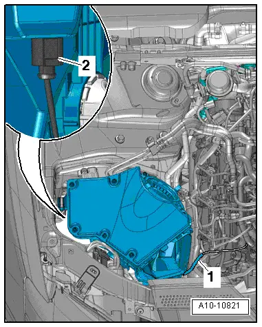
–  Disconnect vacuum line -1-.
–  Detach air cleaner housing and, if fitted, unplug electrical connector -2- at variable intake manifold change-over valve -N335- on reverse side of air cleaner.
  A10-10821
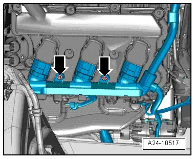
–  Remove bolts -arrows- on cylinder head (right-side) and unplug electrical connectors at ignition coils.
  A24-10517
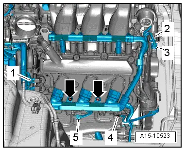
–  Unplug electrical connector -5- at Hall sender 3 -G300-.
  Note
Disregard items marked -2, 3 and 4-.
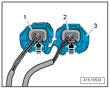
–  Press both catches and pull both connectors -1- off camshaft control valve 1 -N205- and exhaust camshaft control valve 1 -N318-.
  Note
  A15-10523
The connecting piece -3- (only on some versions) on the electrical connectors -1- and -2- for the camshaft control valves is intended to prevent the connectors from being interchanged by mistake; it should therefore not be separated from the connectors.
–  Move wiring harness clear to the side.
  A15-10524
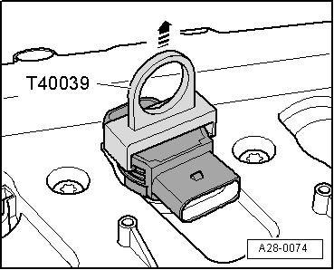
–  Remove ignition coils using puller -T40039-.
  A28-0074
Rest-of-world vehicles:
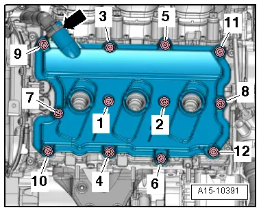
–  Disconnect crankcase breather hose -arrow- by pressing release tabs.
–  Remove bolts in the sequence -12 ... 1- and remove cylinder head cover (right-side).
USA models:
  Caution
Risk of violating emission legislation applying to USA models.
Do NOT open hose connection -arrow-.
–  Remove bolts in the sequence -12 ... 1- and move cylinder head cover (right-side) clear to one side with crankcase breather hose -arrow- still connected.
Installing
l  Tightening torque → Fig..
Installation is carried out in the reverse order; note the following:
  Note
t  Renew gasket for cylinder head cover if damaged.
t  Renew bolts for cylinder head cover if seals on bolts are damaged.
–  Clean sealing surfaces; they must be free of oil and grease.
–  Tighten bolts for cylinder head cover (right-side) → Fig..
  A15-10391

Removing and installing cylinder heads > < Removing and installing cylinder head cover (left-side)