audi Workshop Repair Guides

Audi Workshop Service and Repair Manuals

Removing and installing subframe cross brace > < Exploded view of subframe, cross brace, anti-roll bar, coupling rod, subframe shield
Removing and installing subframe
Special tools and workshop equipment required
   
t  Support bracket -10-222 A-
  W00-0225
t  Engine support supplement set -T40093- may be required, depending on engine version. For a detailed description of the steps required to support the engine, refer to → Rep. gr.10.
  W00-10354
t  Engine and gearbox jack -V.A.G 1383 A-
  W00-0120
t  Support -T10149-
  W00-1297
t  Tensioning strap -T10038-
Removing
–  Remove wheels.
–  Remove left and right wheel housing liner → Rep. gr.66.
–  Remove noise insulation → Rep. gr.66.
–  Remove cross brace → Chapter.
–  If fitted, remove subframe shield (left and right) → Chapter.
–  Remove anti-roll bar → Chapter.
–  Remove vehicle level senders, if fitted → Chapter.
  W00-1005
–  Tie up wheel bearing housing with tensioning strap -T10038- on both sides as shown in illustration.
–  Remove track control link on both sides → Chapter.
–  Remove steering box → Chapter.
–  Take up full weight of engine with support bracket → Rep. gr.10.
t  Support bracket -10-222 A-
t  Engine support supplement set -T40093- may be required, depending on engine version. For a detailed description of the steps required to support the engine, refer to → Rep. gr.10.
  A40-10229
–  Unscrew left and right bolts -1- and nuts -3- and take out longitudinal struts -2-.
  A10-10844
–  Detach bolt connection -1-.
–  Swivel out guide link and tie up to body with wire or similar.
  A40-10215
–  On vehicles with electro-hydraulic engine mountings, unplug connector -arrow- for left electro-hydraulic engine mounting solenoid valve -N144- and right electro-hydraulic engine mounting solenoid valve -N145-.
–  Depending on engine version, unscrew nut -2- for bracket with electrical wiring on right side of vehicle.
  A40-10226
–  Remove bolt from bracket for power steering line -arrow-.
  A40-10227
–  Remove bolts -1 and 5- for engine mounting (left and right).
–  Move aside retaining plate -2- for engine mounting (left and right).
–  Before lowering the subframe, check that all electrical wiring has been disconnected.
  A10-10880
  Note
Mark installation position of subframe -A- to -D- using a felt-tip pen or similar.
–  Remove bolts -1- to -8- and take out subframe.

Installing
Installation is carried out in the reverse sequence. Note the following points:
Tightening torques → Chapter „Exploded view of subframe, cross brace, anti-roll bar, coupling rod, subframe shield“
Tightening torques → Chapter „Exploded view of suspension strut with mounting bracket, shock absorber fork, upper links, body brace“
Tightening torques → Chapter „Exploded view of track control link, swivel joint, guide link, vehicle level sender“
Tightening torques → Chapter „Exploded view of wheel bearing housing, wheel bearing unit“
   
Procedure for attachment of subframe:
–  Fit subframe and align with markings -A- and -B- made earlier. Tighten bolts -2- and -3- to specified torque setting (but do NOT turn further through specified angle).

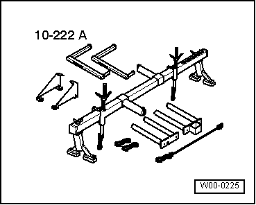
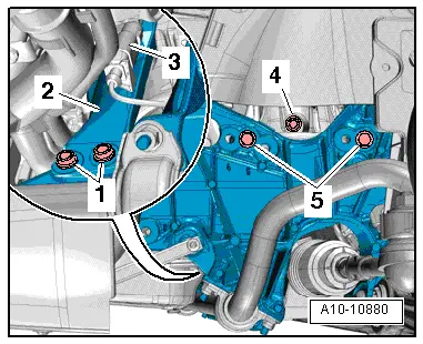
–  Press subframe into place at markings -C- and -D-. Tighten bolts -5- and -8- to specified torque.
–  Screw in bolts -1-, -4-, -6- and -7- and tighten to specified torque.
–  Tighten bolts -1- to -8- through specified angle to final setting.
  Note
t  Bonded rubber bushes can only be turned to a limited extent. The suspension mountings must therefore only be tightened when the suspension is in the unladen position or reference position.
t  Lifting suspension to unladen position → Chapter „Lifting suspension to unladen position (vehicles with coil springs)“
–  On vehicles with automatic headlight range control, carry out basic adjustment of headlights → Rep. gr.94.
–  If, on vehicles with electronic damping control, the vehicle level sender has been removed and refitted or the linkage detached, the reference position must be re-adapted → Chapter. → Vehicle diagnostic, testing and information system VAS 5051
–  If the reference position has been re-adapted on vehicles with lane departure warning, the lane departure warning control unit -J759- must be recalibrated → Chapter.
–  Secure wheel → Wheels and tyres; Rep. gr.44.
–  Wheel alignment must be checked and adjusted, see chart → Chapter.
   

Removing and installing subframe cross brace > < Exploded view of subframe, cross brace, anti-roll bar, coupling rod, subframe shield