Audi Workshop Service and Repair Manuals
HOME
FEATURES
MENU
INDEX
ABOUT US
Exploded view of drive shaft with 88 mm dia. outer constant velocity joint and 100 mm dia. inner sliding constant velocity joint >
< Slackening and tightening bolt securing drive shaft to wheel hub
A4 Mk3
Running gear, front-wheel drive and four-wheel drive
Rear suspension, drive shaft
Drive shaft
Removing and installing drive shaft
Removing and installing drive shaft
Removing and installing drive shaft
Removing
–
Slacken bolt securing drive shaft to wheel hub
→ Chapter
.
–
Remove wheel.
–
Remove coil spring
→ Chapter
.
–
Remove rear silencer(s) with brackets
→ Rep. gr.26
.
–
Remove rear final drive
→ Rep. gr.39
.
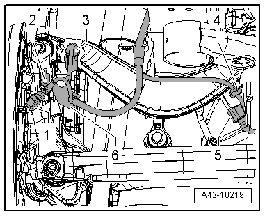
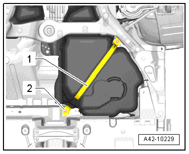
Applies only to left drive shaft:
–
Re-attach tensioning strap
-1-
. Tighten bolt
-2-
only hand-tight.
–
Release and unplug connector
-5-
from rear left vehicle level sender -G76-.
–
If fitted, unclip wiring harness
-4-
.
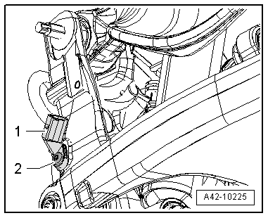
Drive shafts on both sides (continued):
–
Remove bolt
-2-
and detach rear speed sensor
-1-
.
–
Take out drive shaft from the inside.
Installing
Installation is carried out in the reverse sequence. Note the following points:
Tightening torque for drive shaft
→ Chapter „Exploded view of drive shaft with 88 mm dia. outer constant velocity joint and 100 mm dia. inner sliding constant velocity joint“
Tightening torque for drive shaft
→ Chapter „Exploded view of drive shaft with 100 mm dia. outer constant velocity joint and 108 mm dia. inner sliding constant velocity joint“
–
Install rear final drive
→ Rep. gr.39
.
–
Install rear silencer(s) with brackets
→ Rep. gr.26
.
–
Attach fuel tank tensioning strap
→ Rep. gr.20
.
–
Install coil spring
→ Chapter
.
–
Install rear speed sensor
→ Rep. gr.45
.
–
Secure wheel
→ Wheels and tyres; Rep. gr.44
.
–
Tighten bolt securing drive shaft to wheel hub
→ Chapter
.
Running gear, front-wheel drive and four-wheel drive
Rear suspension, drive shaft
Drive shaft
Removing and installing drive shaft
Exploded view of drive shaft with 88 mm dia. outer constant velocity joint and 100 mm dia. inner sliding constant velocity joint >
< Slackening and tightening bolt securing drive shaft to wheel hub