
A4 Mk3
| Exploded view of drive shaft with 88 mm dia. outer constant velocity joint and 100 mm dia. inner sliding constant velocity joint |
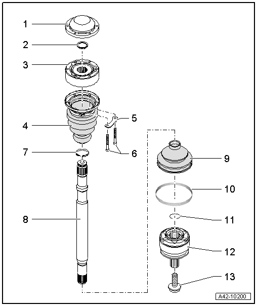
| 1 - | Cover |
| q | Drive off cover carefully with drift |
| q | Always renew |
| q | Sealing surfaces between cover and inner CV joint must be free from grease on assembly |
| q | Before attaching to constant velocity joint, apply sealant to sealing surface → Anchor |
| 2 - | Circlip |
| q | Use normal commercial circlip pliers when removing and installing |
| q | Always renew |
| 3 - | Inner sliding constant velocity joint |
| q | Outside diameter: 100 mm |
| q | Renew only as complete unit |
| q | Checking → Chapter |
| q | Pressing off → Chapter |
| q | Pressing on → Anchor |
| q | Grease quantity and type → Anchor |
| q | Sealing surfaces between cover and inner CV joint and between boot and inner CV joint must be free from grease on assembly |
| q | Grease splines on drive shaft lightly with grease used in joint when fitting joint onto drive shaft |
| 4 - | Boot with cap for inner sliding constant velocity joint |
| q | Without vent hole |
| q | Drive cap off carefully with drift |
| q | Always renew |
| q | Check inner constant velocity joint if boot is damaged → Chapter |
| q | Before attaching to constant velocity joint, apply sealant to sealing surface → Anchor |
| q | Align cover with bolt holes |
| q | Sealing surfaces between boot and inner CV joint must be free from grease on assembly |
| q | Sealing surfaces between boot and drive shaft must be free from grease on assembly |
| q | Briefly lift boot to equalise pressure before tightening hose clip |
| 5 - | Lock plate |
| 6 - | Bolt |
| q | 20 Nm +90° |
| q | Always renew if removed |
| 7 - | Hose clip |
| q | Always renew |
| q | Tightening → Anchor |
| 8 - | Drive shaft |
| q | Removing and installing → Chapter |
| 9 - | Boot for outer constant velocity joint |
| q | Without vent hole |
| q | Check for splits and chafing, renew if necessary |
| q | Check outer constant velocity joint if boot is damaged → Chapter |
| q | Sealing surfaces between boot and outer CV joint must be free from grease on assembly |
| q | Sealing surfaces between boot and drive shaft must be free from grease on assembly |
| q | Briefly lift boot to equalise pressure before tightening hose clip |
| 10 - | Hose clip |
| q | Unfastening → Anchor |
| q | Tightening → Anchor |
| 11 - | Circlip |
| q | Always renew |
| q | For correct version refer to → Electronic parts catalogue |
| q | Fit into annular groove on shaft before installing (no longer visible once joint is installed) |
| q | Before fitting the constant velocity joint, align the circlip centrally with the opening facing upwards |
| 12 - | Outer constant velocity joint |
| q | Outside diameter: 88 mm |
| q | Renew only as complete unit |
| q | Checking → Chapter |
| q | Driving off → Chapter |
| q | Installing: drive onto shaft with plastic hammer until compressed circlip seats |
| q | Circlip must fit in chamfer on joint when installing; guide with pliers if necessary |
| q | Grease quantity and type → Anchor |
| q | Sealing surfaces between boot and outer CV joint must be free from grease on assembly |
| q | Grease splines on drive shaft lightly with grease used in joint when fitting joint onto drive shaft |
| 13 - | Bolt |
| q | Always renew |
| q | Observe instructions for loosening and tightening → Chapter |
| q | 200 Nm +180° |
 Note
Note
|
| Grease quantity | of which in: | ||
| Outer joint | Total quantity | Joint | Boot |
| [mm] | [g] | [g] | [g] |
| 88 | 90 | 40 | 50 |
| Inner joint | Put in grease through ball bearing races | ||
| 100 | 90 | ||