| –
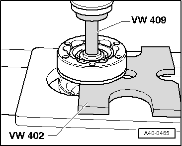
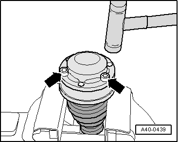
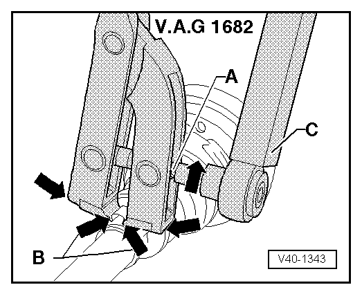
| Using bolts -arrows-, align new cover in relation to bolt holes. |
| The alignment must be very accurate, because no further alignment is possible once the part has been hammered on. |
| –
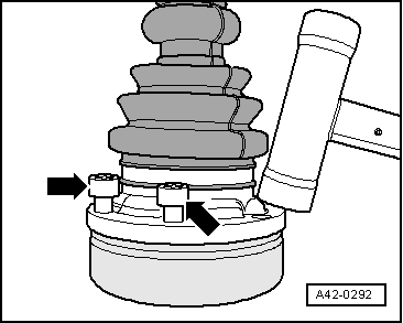
| Drive on cover using a plastic hammer. |
| –
| Remove surplus sealant immediately as it is pressed out. |
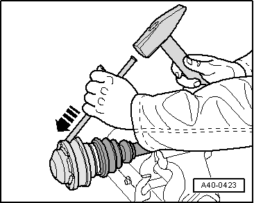
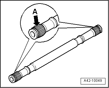
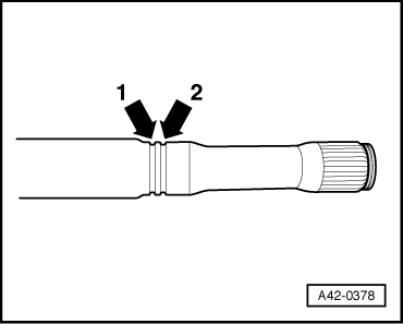
| Inner sliding constant velocity joint (100 mm dia.) |
| –
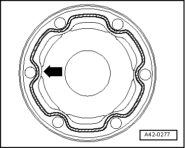
| Pack 40 g of drive shaft grease into joint through ball races. |
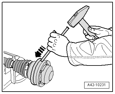
| Inner sliding constant velocity joint (108 mm dia.) |
| –
| Pack 70 g of drive shaft grease into joint through ball races. |
|
|
|