audi Workshop Repair Guides

Audi Workshop Service and Repair Manuals

Checking outer constant velocity joint > < Servicing outer sliding constant velocity joint (88 mm or 98 mm dia.)
Servicing inner sliding constant velocity joint with cap (100 mm or 108 mm dia.)
Special tools and workshop equipment required
   
t  Thrust plate -VW 401-
  W00-0135
t  Thrust plate -VW 402-
  W00-0136
t  Press tool -VW 408 A-
  W00-0022
t  Support sleeve -VW 522-
t  Circlip pliers (commercially available)
t  Copper or brass drift
t  Sealant → Electronic parts catalogue
  W00-0152
Removing inner sliding constant velocity joint (100 mm or 108 mm dia.)
–  Clamp drive shaft in vice using protective jaw covers.
–  Drive off cover with a copper or brass drift.
  A40-0423
–  Drive off cap with a copper or brass drift.
–  Unfasten and detach only the „small“ hose clip.
  A42-10231
–  Remove circlip.
  A42-0290
–  Press inner sliding constant velocity joint off drive shaft using tools shown in illustration.
1 - Thrust plate -VW 401- or thrust plate -VW 402-
2 - Press tool -VW 408 A-
–  Pull boot off drive shaft.
Installing inner sliding constant velocity joint (100 mm or 108 mm dia.)
–  Push boot with „small“ hose clip onto drive shaft.
  A42-10319
–  Grease splines -A- on drive shaft lightly with grease used in joint before fitting joint body onto drive shaft.
  A42-10049
–  Clamp drive shaft in vice using protective jaw covers.
–  Carefully fit joint onto drive shaft and drive home onto stop with a hammer, making use of the support sleeve -VW 522-.
1 - Protective jaw covers
2 - Inner sliding constant velocity joint
3 - Support sleeve -VW 522-
If there is a chamfer on the internal diameter of the ball hub (splines), it should face the contact collar of the drive shaft.
  A42-10320
–  Fit a new circlip.
–  Check that circlip is properly seated.
–  Before fitting boot, pack half the drive shaft grease provided into joint from boot side of joint.
–  Degrease contact surface for cover.
  A42-0290
–  Apply sealant (hatched area) to clean surface on inside of cap on CV joint boot.
–  Apply a continuous sealant bead of Ø 2 - 3 mm.
–  Route sealant bead around inside of holes -arrow-.
–  Use sealant → Electronic parts catalogue.
  A42-0277
Boot and contact surface of cap must be free of grease.
–  Align cap and bolts -arrows- with bolt holes.
The alignment must be very accurate, because no further alignment is possible once the part has been hammered on.
–  Drive on cover using a plastic hammer.
–  Remove surplus sealant immediately as it is pressed out.
–  Pack remainder of drive shaft grease into constant velocity joint through ball races.
  A42-0292
–  Degrease contact surface for cover and for constant velocity joint.
–  Apply sealant -hatched area- to clean inner surface of cover.
–  Apply a continuous sealant bead of Ø 2 - 3 mm.
–  Route sealant bead around inside of holes -arrow-.
–  Use sealant → Electronic parts catalogue.
  A42-0277
–  Align cover and bolts -arrows- with bolt holes.
The alignment must be very accurate, because no further alignment is possible once the part has been hammered on.
–  Drive on cover using a plastic hammer.
–  Remove surplus sealant immediately as it is pressed out.
  A40-0439
Boot and drive shaft must be free from grease.
–  Push joint boot onto drive shaft.
Boot and drive shaft must be free from grease.
–  Position boot between -arrows-.
Disregard item -1-.
–  Make sure boot is properly positioned on drive shaft.
–  Tighten hose clips on inner joint.
Tightening hose clips on inner joint
  Note
When installing the large hose clip, position the fastener between two holes.
Use the following tools depending on type of hose clip:
Special tools and workshop equipment required
  A42-0377
t  Pliers -3340-
  W00-0102
t  Clamp tensioner -V.A.G 1682-
  W00-0448
t  Torque wrench -V.A.G 1331-
  W00-0427
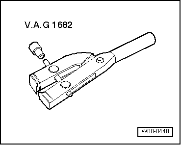
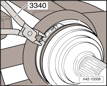
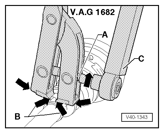
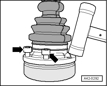
Use clamp tensioner -V.A.G 1682- to fit and tighten stainless steel clips, as shown in illustration.
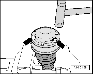
–  Apply clamp tensioner -V.A.G 1682- as shown. Ensure jaws of tool make contact with lugs -arrows B- on hose clip.
–  Tighten clip by turning spindle with torque wrench -C- (take care to keep tool straight).
t  
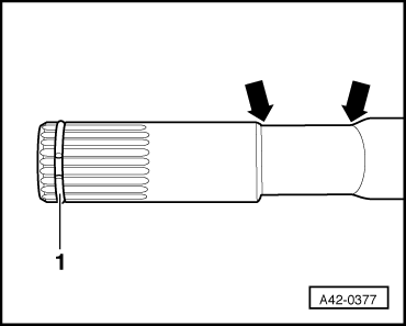
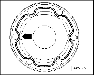
Due to the hard material of the CV joint boot (as opposed to rubber), a stainless steel hose clip is required; this can only be tightened using clamp tensioner -V.A.G 1682-.
t  Tightening torque: 20 Nm.
t  
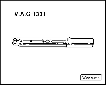
Use torque wrench with 5…50 Nm adjustment range (e.g. -V.A.G 1331-).
t  
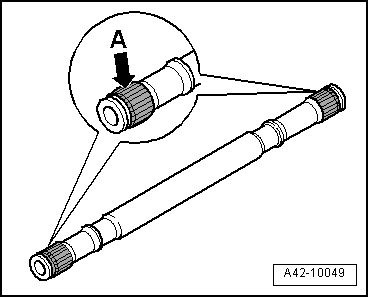
Make sure thread of spindle on tool -A- turns freely. Lubricate with MoS2 grease if necessary.
t  If the thread is stiff (e.g. due to dirt), the required clamping force will not be attained at the hose clip when the specified tightening torque is applied.
  V40-1343
Use pliers -3340- to fit and tighten clips with retaining lugs, as shown in illustration.
–  Engage hose clip by hand at first lug.
–  Use pliers -3340- to fasten hose clip.
  A42-10008

Checking outer constant velocity joint > < Servicing outer sliding constant velocity joint (88 mm or 98 mm dia.)