| Removing and installing battery cooling module |
| Vehicles with a high-voltage system (hybrid vehicles) |
| As work in the vicinity of high-voltage system components is necessary for the following sequence of operations, perform „Visual inspection of high-voltage components and cables for damage“ → Chapter and heed the „General warnings for working on high-voltage system“ → Electrical system; Rep. gr.93 |

WARNING | Danger from unexpected engine starting |
| When performing general work on vehicles with a high-voltage system, switch off the ignition and remove the ignition key from the passenger compartment. |
|

WARNING | Working on vehicles with high-voltage wiring: |
| l
| Do not support yourself or tools on high-voltage wiring or associated components --> this can damage the insulation. |
| l
| High-voltage wiring must not be excessively bent or kinked --> this can damage the insulation. |
| l
| The round high-voltage connectors are colour-coded with an external coloured ring and are provided with mechanical coding or guide lugs. It is important to observe this coding when joining up the round high-voltage connectors, otherwise the connectors can be damaged. |
|

DANGER! | Risk of fatal injury if high-voltage components are damaged. |
| Observe the following when working in the vicinity of high-voltage components or wiring: |
| t
| It is not permitted to use cutting or forming tools, other sharp-edged tools or heat sources such as welding, brazing, soldering, hot air or thermal bonding equipment. |
| t
| Before starting work, visually inspect the high-voltage components in the areas involved. |
| t
| Before working in the engine compartment, visually inspect the power electronics -JX1-, electric drive motor -V141-, air conditioner compressor -V470- and high-voltage wiring. |
| t
| Before working on the vehicle underbody, visually inspect the high-voltage wiring and covers. |
| t
| Before working on the rear section of the vehicle, visually inspect the high-voltage wiring and the electro-box with the maintenance connector for high-voltage system - TW -. |
| t
| Visually inspect all potential equalisation lines. |
| Check the following when making the visual inspection: |
| t
| There must be no external damage on any component. |
| t
| The insulation of the high-voltage wiring and potential equalisation lines must not be damaged. |
| t
| There must be no unusual deformation of the high-voltage wiring. |
| t
| All high-voltage components must be identified by a red warning sticker. |
|
| –
| Switch off the ignition. |
| –
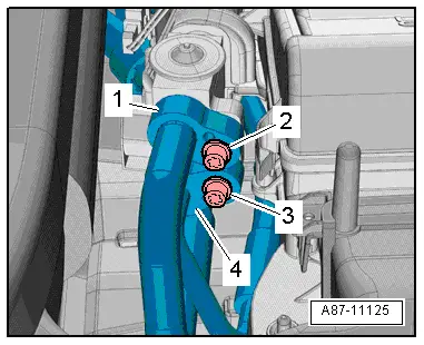
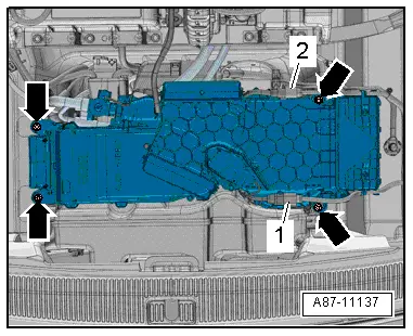
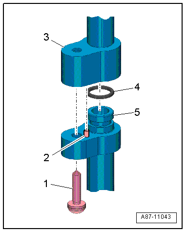
| Remove the supply air duct for the drive battery → Chapter. |
|
|
|
 Note
Note
 Note
Note
 Note
Note
 Note
Note
 Note
Note
 Note
Note