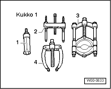
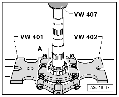
audi Workshop Repair Guides

Audi Workshop Service and Repair Manuals

Final drive, differential, differential lock > < Output shaft
Dismantling and assembling input shaft - assembly sequence
   
Dismantling and assembling input shaft - assembly sequence
Special tools and workshop equipment required
t  Drift sleeve -VW 244 B-
t  Thrust plate -VW 401-
t  Thrust plate -VW 402-
t  Press tool -VW 407-
t  Press tool -VW 412-
t  Thrust piece -VW 434-

   
t  Thrust piece -VW 454-
t  Installing sleeve -VW 455-
t  Tube -VW 519-
t  Drift sleeve -40 - 21-
t  Support bridge -2011-
t  Wheel bearing tube -3345-

   
t  -3-Splitter -Kukko 17/2-
  W00-0633
t  Inductive heater -VAS 6414-
t  Depth gauge
Dismantling input shaft
l  Input shaft has been detached from output shaft and bearing mounting → Chapter.
l  Bolt in input shaft has been loosened and removed → Anchor.
  W00-10814
–  Press off 3rd speed, 4th speed and 6th speed selector gears together with synchronising hub for 3rd/4th gear and needle bearing inner races.
A - Splitter 22...115 mm, e.g. -Kukko 17/2-
  Note
Support splitter -A- against 6th speed selector gear so that 5th/6th gear locking collar is not pulled off at the same time.
–  Detach circlip for 5th /6th gear synchronising hub from input shaft.
  Note
Mark this circlip so that it is not interchanged with the circlip below the 5th /6th gear synchronising hub.
  A35-10114
–  Press off locking collar with 5th/6th gear synchronising hub and 5th speed selector gear.
  A35-10115
–  Open out needle bearing -2- for 5th gear and guide it carefully over circlip -1- and teeth -3- for 5th/6th gear synchronising hub.
  Note
t  The circlip -1- below teeth -3- for the 5th/6th gear synchronising hub should only be removed from the input shaft if the roller bearing is being renewed (next step).
t  Always renew the circlip if it has been removed.
–  Remove circlip -1-.
  A35-10116
–  Press roller bearing off input shaft.
A - Splitter 22...115 mm, e.g. -Kukko 17/2-
  Note
t  The roller bearing will be damaged when it is pressed off and must therefore always be renewed.
t  To press off the roller bearing, you can also break open the cage of the bearing using a screwdriver or similar and then apply the splitter to the inner race.
–  Clean thread for bolt in input shaft to remove any remaining locking fluid.
Assembling input shaft
  Note
t  
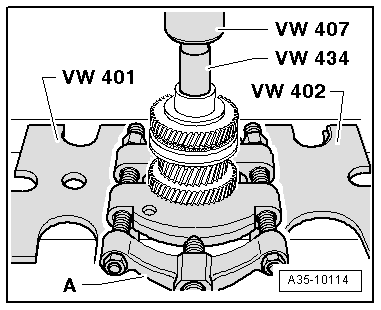
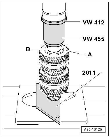
Lubricate all needle bearings and synchro-rings with gear oil before fitting.
t  
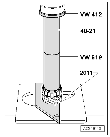
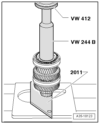
Heat needle bearing inner races to 130 °C (max.) before pressing on (wear protective gloves).
t  
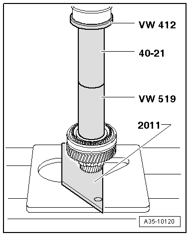
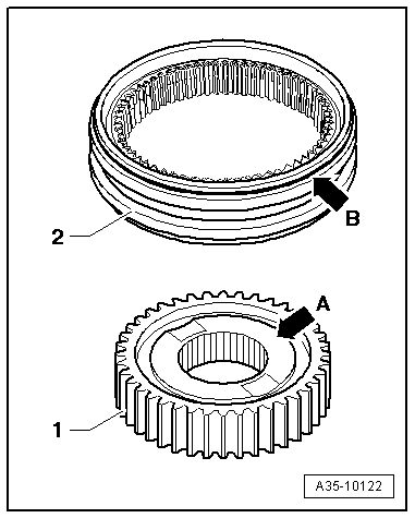
Heat synchronising hubs to 100 °C (max.) before pressing on (wear protective gloves).
t  
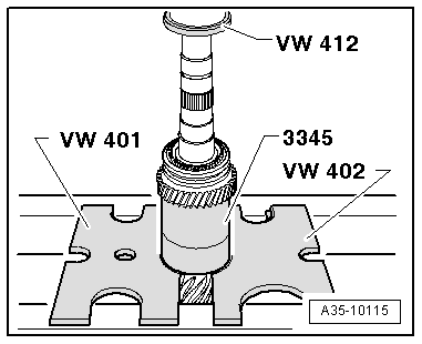
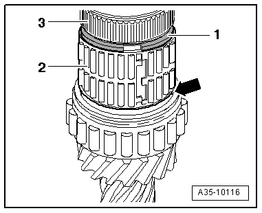
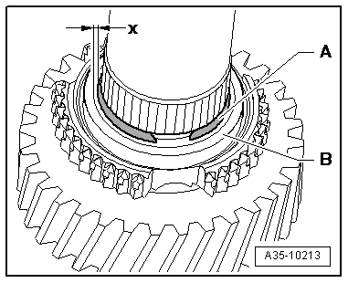
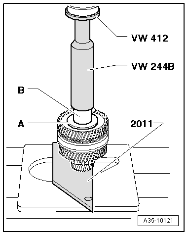
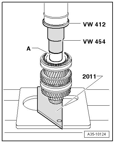
Always press on roller bearing, needle bearing inner races and synchronising hubs as far as stop to make sure the axial clearance of the selector gears meets the specification.
  A35-10117
Inserting spring in selector gear
The bent end of the spring -arrow- must be hooked into the hole in the selector gear.
  V35-1036
Checking synchro-ring for wear
–  Press synchro-ring -E- into locking collar and measure gap -a- at positions -A-, -B- and -C- using depth gauge -D-.
–  Add the measured values and divide by 3.
The determined value should not exceed 0.5 mm.
  Note
If components are not being renewed, make sure they are re-installed on the same gear.
  A35-10147
–  Press roller bearing onto input shaft as far as stop.
  A35-10118
–  Carefully open out new circlip -1- and guide it over teeth for 5th/6th gear synchronising hub -3-.
l  It should not be possible to turn the circlip in the annular groove on the input shaft by hand
–  Open out needle bearing -2- for 5th speed selector gear and guide it carefully over circlip -1-; do not seat needle bearing on shoulder -arrow- of input shaft.
  A35-10116
–  Install 5th speed selector gear -B-.
l  When rotated, selector gear -B- must not come into contact with circlip -A-.
l  There must be a uniform clearance -x- between selector gear and circlip all round.
–  Fit 5th gear synchro-ring.
  A35-10213
Installation position of 5th/6th gear synchronising hub and locking collar
l  The shorter teeth -arrow A- above the annular groove -arrow B- of synchronising hub -1- must face towards 6th speed selector gear.
l  The groove -arrow C- on the face of locking collar -2- must face towards 6th gear.
–  Slide locking collar -2- over synchronising hub -1-.
Note the following when performing the following steps:
–  Fit input shaft in drilling of support bridge -2011-.
–  Position drift sleeves on centre of heated components (synchronising hub and needle bearing inner races).
–  First press on components just briefly, then stop exerting pressure and check whether drift sleeves are still positioned properly and press on as far as stop.
  A35-10119
Pressing on 5th and 6th gear synchronising hub with locking collar
  A35-10120
Determining thickness of circlip for synchronising hub for 5th and 6th gear
l  Synchronising hub is pressed on as far as stop.
–  Determine the thickest circlip that will just fit and install it. For part number refer to → Electronic parts catalogue.
The following circlips are available:
  V35-1347
Circlip thickness (mm)
2.442.472.50

–  Install 6th speed selector gear with needle bearing and synchro-ring.
   
–  Fit thrust washer -A-.
–  Press on needle bearing inner race -B- for 3rd speed selector gear.
–  Install 3rd speed selector gear with needle bearing and synchro-ring.
  A35-10121
Installation position of 3rd/4th gear synchronising hub and locking collar
l  The lower inside collar -arrow A- of the synchronising hub faces 4th gear.
l  The groove -arrow B- on the face of locking collar -2- must face towards 4th gear.
–  Slide locking collar -2- over synchronising hub -1-.
  A35-10122
Pressing on 3rd and 4th gear synchronising hub with locking collar
  A35-10123
Pressing on needle bearing inner race -A- for 4th speed selector gear
–  Install 4th speed selector gear together with needle bearing and synchro-ring.
  A35-10124
–  Fit thrust washer -A-.
–  Press on inner race -B- for roller bearing.
–  Then check all selector gears for freedom of movement and axial play.
l  The axial play of the selector gears must be at least 0.15 mm.
  Note
Tighten bolt securing input shaft to specified torque → Anchor.
  A35-10125

Final drive, differential, differential lock > < Output shaft