
Park Avenue V6-3.8L SC VIN 1 (2005)
9. Stake 3 places 120 degrees apart.
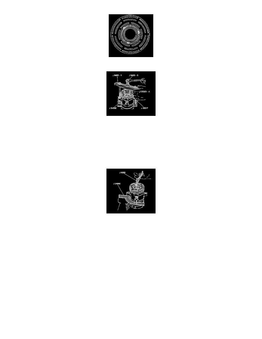
10. With the compressor mounted to the J 34992 , position the rotor and bearing assembly on the front head.
11. Position the J 33017 and the J 33023-A directly over the inner race of the bearing.
12. Position the J 8433-1 on the J 33023-A.
13. Assemble the 2 through bolts and the washers of the J 34992 through the slots of the J 8433-1.
14. Thread the 2 through bolts into the J 34992.Ensure that the thread of the through bolts engages the full thickness of the J 34992.
15. Tighten the J 8433-3 in the J 8433-1 in order to force the pulley rotor and bearing assembly onto the front head of the compressor.
16. If the J 33017 slips off direct, in-line contact with inner face of the bearing, use the following steps:
1. Loosen the J 8433-3.
2. Realign the J 33017 and the J 33023-A in order to ensure that the installer clears the front head.
17. Install the rotor and bearing assembly retainer ring using the J 6083.
18. Install the clutch plate and hub assembly.
19. Install the A/C compressor.