
Rendezvous FWD V6-3.5L VIN L (2006)
Manifold Pressure/Vacuum Sensor: Testing and Inspection
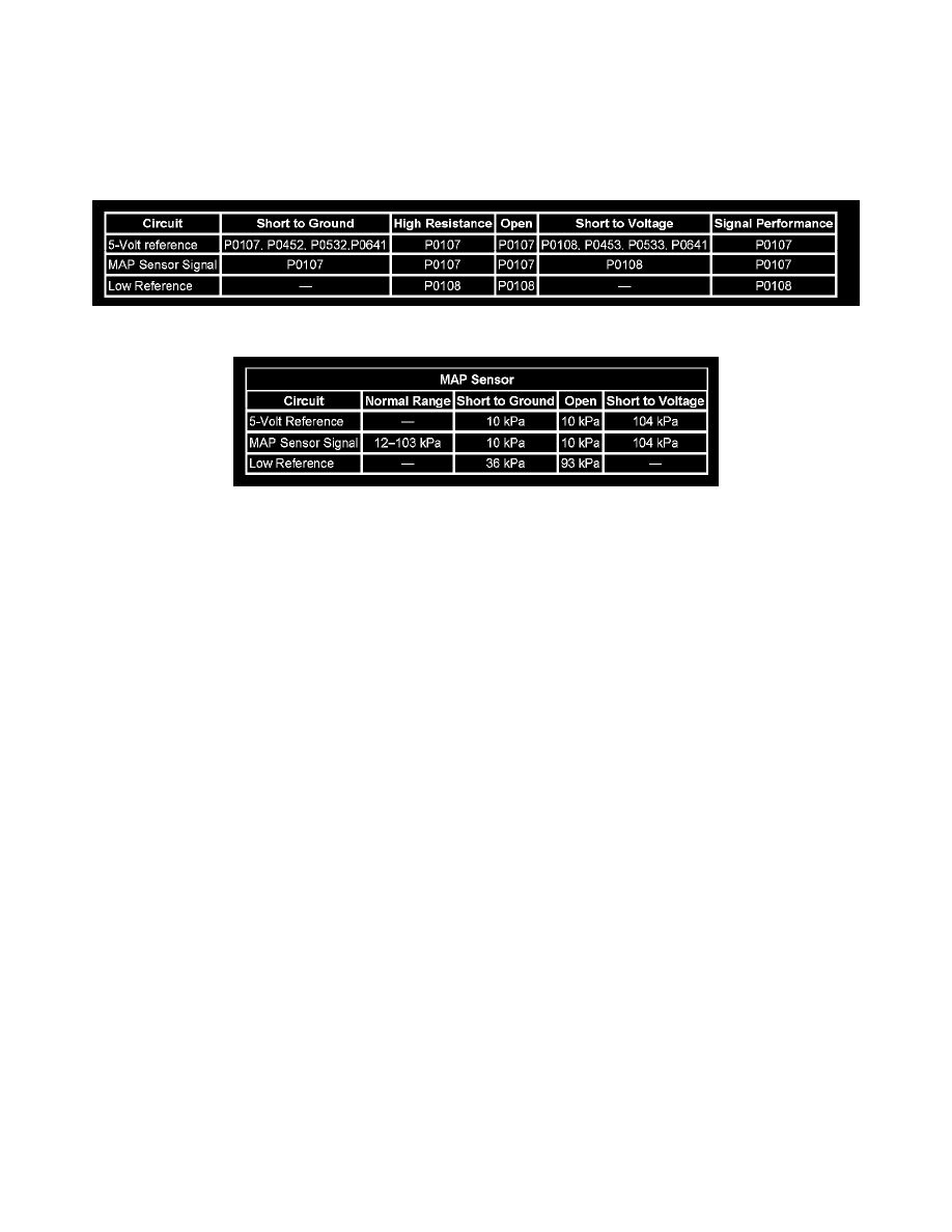
MANIFOLD ABSOLUTE PRESSURE (MAP) SENSOR DIAGNOSIS
DIAGNOSTIC FAULT INFORMATION
IMPORTANT: Always perform the Diagnostic System Check - Vehicle prior to using this diagnostic procedure. See: Testing and
Inspection/Diagnostic Trouble Code Tests and Associated Procedures
TYPICAL SCAN TOOL DATA
MAP Sensor
CIRCUIT/SYSTEM DESCRIPTION
The manifold absolute pressure (MAP) sensor responds to pressure changes in the intake manifold. The pressure changes occur based on the engine
load. The MAP sensor has the following circuits:
-
5-volt reference circuit
-
Low reference circuit
-
MAP sensor signal circuit
The control module supplies 5 volts to the MAP sensor on the 5-volt reference circuit. The control module also provides a ground on the low
reference circuit. The MAP sensor provides a signal to the control module on the MAP sensor signal circuit which is relative to the pressure changes
in the manifold. The control module should detect a low signal voltage at a low MAP, such as during an idle or a deceleration. The control module
should detect a high signal voltage at a high MAP, such as the ignition is ON, with the engine OFF, or at a wide open throttle (WOT). The MAP
sensor is also used in order to determine the barometric pressure (BARO). This occurs when the ignition switch is turned ON, with the engine OFF.
The BARO reading may also be updated whenever the engine is operated at WOT. The control module monitors the MAP sensor signal for voltage
outside of the normal range.
DIAGNOSTIC AIDS
Poor idle characteristics may be due to uncontrolled fueling caused by an open or high resistance in the heated oxygen sensor (HO2S) 1 low signal
circuit. Before replacing any component, ensure that this condition does not exist.
CIRCUIT/SYSTEM TESTING
Always perform the Diagnostic System Check - Vehicle.
1. Start the engine.
2. Monitor the diagnostic trouble code (DTC) information with the scan tool.
3. If DTC P0641 or P0651 is also set, then correct DTC P0641 or P0651 first.
4. Inspect for the following conditions:
-
Disconnected, damaged, or incorrectly routed vacuum hoses
-
MAP sensor disconnected from the vacuum source
-
Restrictions in the MAP sensor vacuum source
-
Intake manifold vacuum leaks
-
Check for a properly functioning oxygen sensor.
5. Turn OFF the ignition.
6. Remove the MAP sensor from the engine vacuum source. Leave the MAP sensor connected to the engine harness.
7. Connect a J 23738-A Mityvac to the MAP sensor.
8. Turn ON the ignition, with the engine OFF.
9. Observe the MAP sensor pressure with the scan tool.
10. Apply vacuum to the MAP sensor with the J 23738-A in 1 inch Hg increments until 15 inches Hg is reached. Each 1 inch Hg should decrease
MAP sensor pressure by 3-4 kPa. Monitor the MAP sensor pressure to see if the decrease in pressure in consistent.