
Corvette V8-5.7L VIN G (1997)
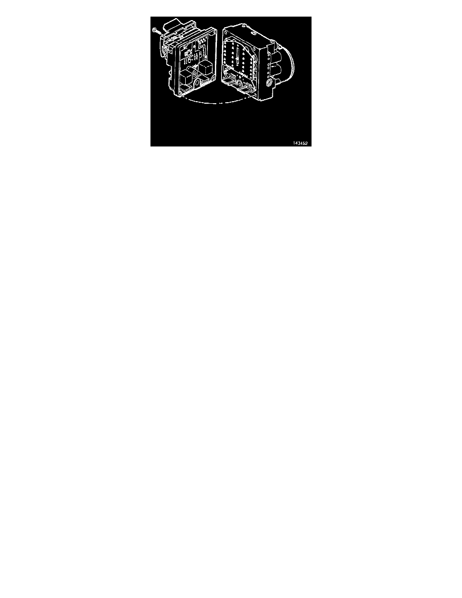
11. Separate the EBTCM from the BPMV by gently pulling apart until separated. Be careful not to damage seal.
INSTALLATION
1. Clean the seal and BPMV gasket surface with alcohol using a clean rag.
2. Install the EBTCM to the BPMV.
-
Tighten the four mounting bolts to 3 Nm (27 inch lbs.), then tighten to 6 Nm (53 inch lbs.).
CAUTION: Use the correct fastener in the correct location. Replacement fasteners must be the correct part number for that application. Fasteners
requiring replacement, or fasteners requiring the use of thread locking compound or sealant are identified in the service procedure. Do not use
paints, lubricants, or corrosion inhibitors on fasteners or fastener joint surfaces unless specified. These coatings affect fastener torque and joint
clamping force and may damage the fastener. Use the correct tightening sequence and specifications when installing fasteners in order to avoid
damage to parts and system.
3. Install the front EBTCM insulator mounting bolt.
-
Tighten the EBTCM insulator mounting bolt to 14 Nm (10 ft. lbs.).
4. Position the EBTCM/BPMV assembly on the vehicle by slipping the BPMV insulator mounting bolts into the left side bracket insulators.
5. Install the right side bracket with the insulator attached to the EBTCM by slipping the bracket insulator over the EBTCM insulator mounting bolt.
-
Tighten if the insulator was removed tighten the insulator bracket nut to 10 Nm (89 inch lbs.).
6. Install the right side bracket to the crossmember by installing the three bolts.
-
Tighten the three bolts to 50 Nm (37 ft. lbs.).
WARNING: MAKE SURE BRAKE PIPES ARE CORRECTLY CONNECTED TO BPMV. IF BRAKE PIPES ARE SWITCHED BY
MISTAKE (INLET vs. OUTLET), WHEEL LOCKUP WILL OCCUR AND PERSONAL INJURY MAY RESULT.
CAUTION: If a new BPMV is being installed, remove the shipping plugs from the valve openings in the compartment during the next step.
7. Install the brake pipes on the BPMV.
-
Tighten the brake pipe fittings to 16 Nm (12 ft. lbs.).
8. Connect the BPMV pump motor ground.
9. Connect the EBTCM harness connector.
NOTE: Both sides of the EBTCM harness connector must be engaged with the lever before closing.
10. Move the stabilizer shaft into position.
11. Install the LH stabilizer shaft insulator clamp.
-
Tighten
-
Upper bolt to 65 Nm (49 ft. lbs.).
-
Lower bolt to 95 Nm (71 ft. lbs.).
12. Install the RH stabilizer shaft insulator clamp.
-
Tighten
-
Upper bolt to 65 Nm (49 ft. lbs.).
-
Lower bolt to 95 Nm (71 ft. lbs.).
13. Turn the ignition switch to the ON position engine OFF.
14. Fill the master cylinder reservoir.
15. Bleed the system.
16. Perform the ABS Diagnostic System Check.