
Luv 2WD L4-110 1800cc (1982)
Positive Crankcase Ventilation: Description and Operation
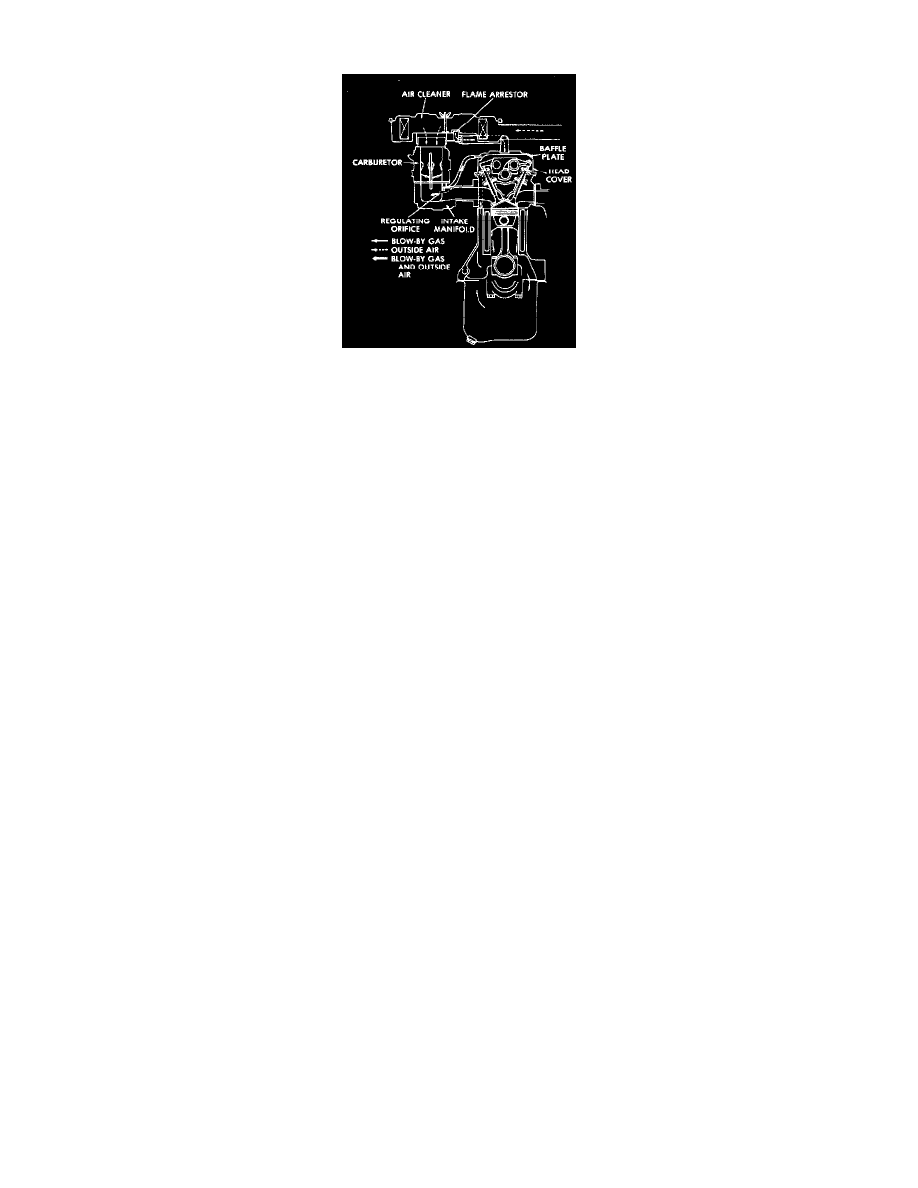
Fig.2 - Positive Crankcase Ventilation System
This system, Fig 2--draws blow-by gases from the crankcase through the intake manifold--where they mix with the air fuel mixture--into the
cylinders--where they are burned in combustion.
-
Blow-by gases are the result of high pressures in the combustion chambers forcing gases past the valves and/or rings during combustion.
This closed type system consists of a baffle plate to separate oil particles from the blow-by gases, a regulating valve or orifice to control the flow
of blow-by gases, a hose to direct fresh air from the air cleaner into the system, and hoses connecting the various components.
During normal engine operation, blow-by gases and fuel vapor emitted from the fuel tank are mixed in the engine with fresh air supplied from the
air cleaner. Oil particles are separated from this mixture by the baffle oil separator located on the camshaft carrier side cover, or built into the
center of the head cover. The blow-by gases are then drawn through the regulating valve or regulating orifice, through the intake manifold, into the
engine for reburning.
During wide open throttle engine operation the negative pressure within the intake manifold is not high enough to draw all the blow-by gases
through the intake manifold so a portion of the blow-by gases are drawn into the air cleaner side cover.
The flow control orifice or regulating valve (PCV), regulates the flow of blow-by gases in response to negative pressures (vacuum) developed in
the intake manifold under varying engine operating conditions.