
Metro L3-061 1.0L VIN 6 TBI (1998)
Intake Manifold: Service and Repair
REMOVAL PROCEDURE
1. Relieve the fuel pressure.
2. Disconnect the negative battery cable.
3. Drain the engine coolant.
4. Remove the air cleaner assembly.
5. Disconnect the following electrical connectors:
^
The engine coolant temperature (ECT) sensor connector
^
The coolant temperature sending unit connector
^
The throttle position (TP) sensor electrical connector
^
The exhaust gas recirculation solenoid vacuum valve
^
The idle speed control (ISC) motor electrical connector
^
The ground wire bolts and ground wires from the intake manifold
^
The throttle body fuel injection (TBI) unit electrical connector
^
The early fuel evaporation (EFE) heater electrical connector (if equipped)
^
The release wiring harness from the retaining clamps
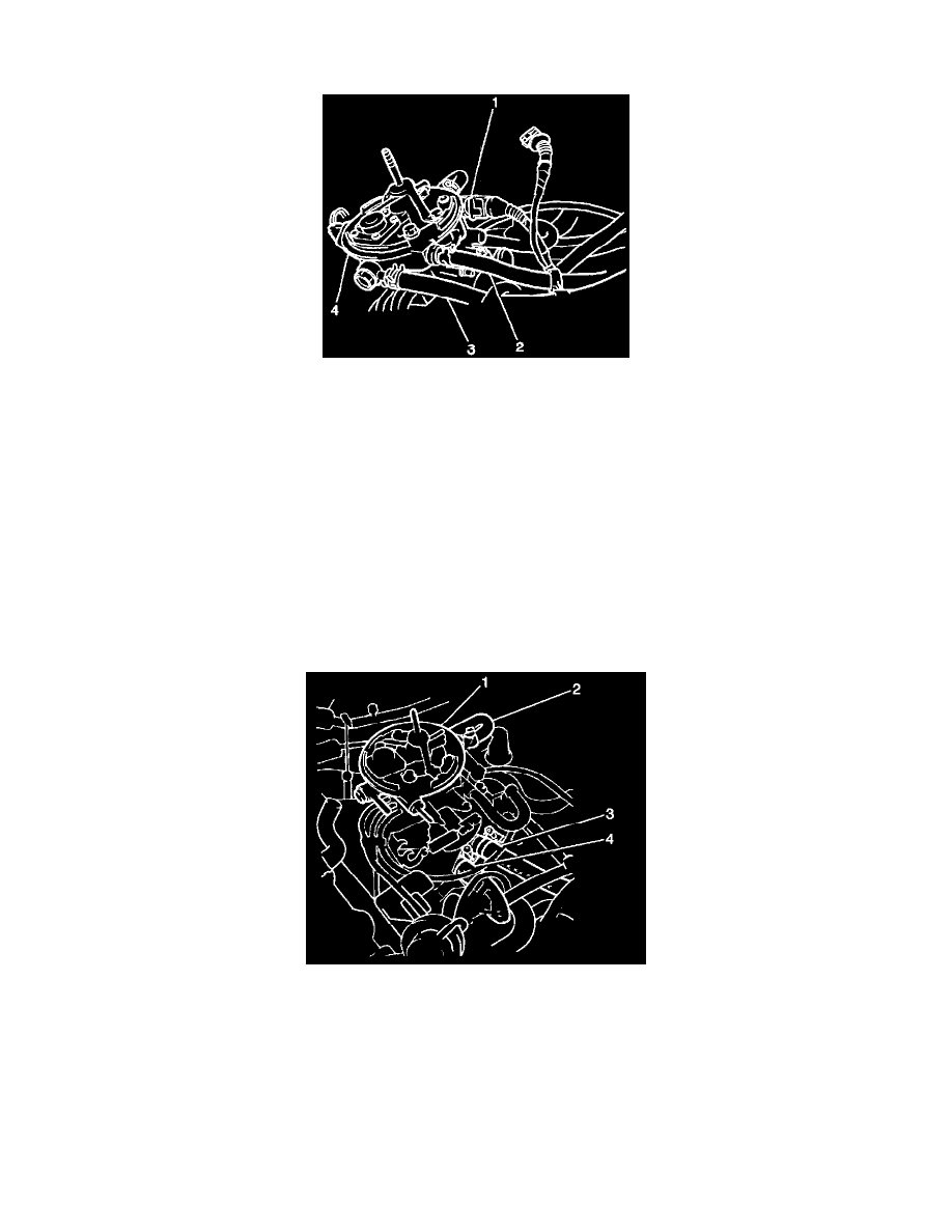
6. Remove the fuel return hose (2) and the fuel feed hose (3) from the TBI unit (4).
7. Remove the coolant hoses (2, 3, and 4) from the TBI unit and the intake manifold.
8. Remove the EGR modulator.
9. Remove the EGR valve.
10. Remove the following vacuum hoses:
^
The evaporative emissions (EVAP) canister hose from the EVAP canister pipe.
^
The manifold absolute pressure sensor hose from the throttle body (TB).
^
The brake booster hose from the intake manifold.