
Tracker 2WD L4-1.6L VIN 6 (2000)
Camshaft Position Sensor: Description and Operation
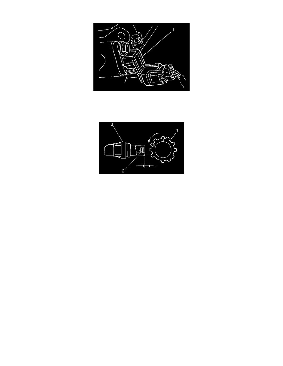
Camshaft Position (CMP) Sensor
The Camshaft Position (CMP) Sensor (1) is located on the back of engine head (3). The PCM uses the CMP sensor input in order to control the fuel
injectors and the ignition timing. The CMP sensor is not adjustable.
Operation
Operation
The camshaft position (CMP) sensor (3) contains a signal generator (hall switch) (2). A signal rotor (2), with 11 notches, is located in the CMP sensor
housing and is driven by the camshaft. The CMP sensor has a specified air gap between the sensor core end and the signal rotor. When the signal rotor
in the housing turns, a magnetic flux from the magnet is applied to the hall element repeatedly. The hall element generates a voltage that is
proportional to the magnetic flux. This voltage signal is wave-shaped and is modified into a digital pulse before being sent to the PCM. The PCM uses
the pulse/revolution signal in determining the engine speed and the position of each cylinder.