
300 V6-3.5L (2008)
a. Adjust Special Tool 8351 (1) Release Probe's gauge pin to extend approximately 20 mm (0.787 in.). Then, carefully insert the release probe
gauge pin into the lash adjuster (6) service access hole (2).
CAUTION: If probe tip (1) breaks off within the lash adjuster (6), replace the affected rocker arm (3).
b. Gently unseat lash adjuster's internal check ball (4).
c. While the internal check ball (4) is held unseated, press the rocker arm (3) into the valve tip (5), allowing the lash adjuster (6) to fully collapse.
Hold this fully collapsed position for about one second, or longer.
d. Slowly release the rocker arm (3), thereby allowing the lash adjuster (6) to extend, which in turn refills the high pressure chamber with
non-aerated oil.
e. Remove probe to allow check ball (4) to seat.
f.
Recheck for sponginess. If the lash adjuster (6) sponginess is not completely or nearly eliminated, then repeat procedure.
g. If the spongy condition cannot be removed, replace effected rocker arm(s) (3).
5. For exhaust rocker arm (3) positions:
a. Adjust Special Tool 8351 (1) Release Probe gauge pin to extend approximately 20 mm (0.787 in.). Then, using two release probes, carefully
insert gauge pins into the lash adjuster service access holes.
CAUTION: If probe tip (1) breaks off within the lash adjuster (6), replace the affected rocker arm (3).
b. Gently unseat BOTH lash adjuster's internal check ball (4) at the same time.
c. While the internal check ball (4) is held unseated, press the rocker arm (6) into the valve tip, allowing the lash adjuster to fully collapse. Hold
this fully collapsed position for about one second, or longer.
d. Slowly release the rocker arm (3), thereby allowing the lash adjuster (6) to extend, which in turn refills the high pressure chamber with
non-aerated oil.
e. Remove probes (1) to allow check balls (4) to seat.
f.
Recheck for sponginess. If the lash adjuster (6) sponginess is not completely or nearly eliminated, then repeat procedure.
g. If the spongy condition cannot be removed, replace effected rocker arm(s) (3).
6. Install cylinder head cover(s).
Removal
REMOVAL
CAUTION: The rocker arm shafts are hollow and are used as lubrication oil passages. The rocker arm and shaft assembly on the RIGHT side
of the engine has an oil passage hole from the cylinder head to the third rocker shaft support. The rocker arm shaft assembly on the LEFT side
of the engine has an oil passage hole from the cylinder head to the second rocker shaft support.
1. Remove cylinder head covers. See: Cylinder Head Assembly/Valve Cover/Service and Repair/Cylinder Head Cover - Removal
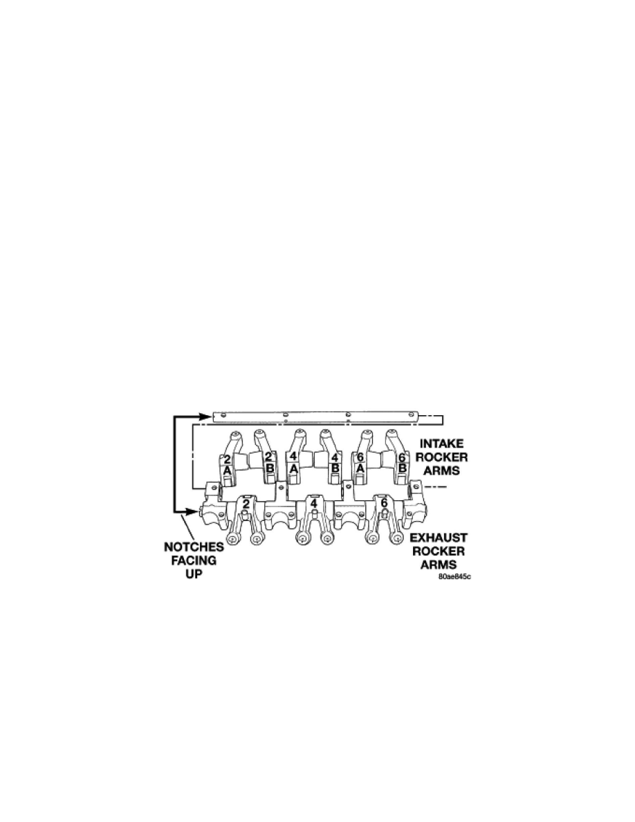
2. Identify the rocker arm assembly and rocker arms before disassembly.
3. Remove rocker arm assembly bolts.
4. Remove rocker arm assembly.
NOTE: To prevent air ingestion into lash adjusters, avoid turning rocker arm assembly upside down.
CAUTION: Do not allow rocker arm assembly to rest on lash adjusters, as damage may occur to lash adjusters and/or plastic retainers.
Disassembly
DISASSEMBLY