
Sebring Convertible V6-2.5L SOHC 24 Valve (1996)
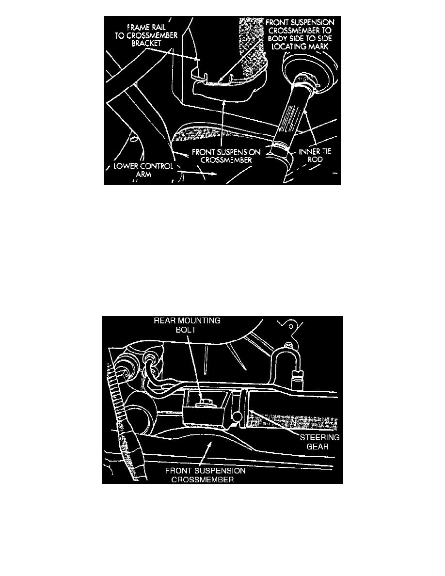
Fig. 7 Front Suspension Crossmember Side To Side Locating Mark
8. Using an awl, scribe a line on front suspension crossmember marking side to side installed location where front suspension crossmember is
mounted against body on both sides of vehicle.
9. Remove stabilizer bar bushing clamp to body attaching bolts only.
10. Remove three ABS control unit bolts, then secure unit to body for suspension crossmember removal. Do not let unit hang by brake tubes.
11. Remove bolts attaching shock absorber clevis to left-hand and right-hand lower control arms.
12. Remove two bolt attaching engine support bracket to front suspension crossmember.
13. Position a suitable jackstand under center of front suspension crossmember.
14. Remove from both sides of vehicle front two bolts attaching front suspension crossmember to frame rail of vehicle, then the rear attaching bolts.
15. Using jackstand, lower front suspension crossmember enough to allow steering gear to be removed from crossmember. Ensure crossmember is
supported by jackstand to avoid damage.
16. Drain power steering fluid, pressure and return hoses from power steering gear assembly.
17. Disconnect power steering harness connector from fluid reservoir switch.
Fig. 8 Steering Gear Rear Mounting Isolator Bolts