
Sebring LXI Sedan V6-2.7L VIN R (2002)
2. Position assembly in an arbor press with Receiving Cup, Special Tool 6758, supporting lower control arm. Then install Remover/Installer, Special
Tool 6804, on the top of the ball joint assembly.
CAUTION: When installing the ball joint in the upper control arm, do not press the ball joint into the control arm all the way. The lip on the ball
joint must not touch the surface of the control arm. Refer to Step 3 below when installing the ball joint.
3. Carefully align all pieces. Using the arbor press, press the ball joint into the control arm until a gap of 3 mm (1/8 inch) is between lip on ball joint
and surface of lower control arm.
4. Reinstall the control arm on the vehicle.
INSTALLATION
1. Align the pivot bar on the upper control arm with the mounting holes in the rear suspension crossmember. Install the pivot bar attaching bolts.
Tighten the 2 pivot bar attaching bolts to a torque of 108 Nm (80 ft. lbs.).
2. Using transmission jack, raise rear suspension crossmember up to the rear frame rails and loosely install the 4 attaching bolts.
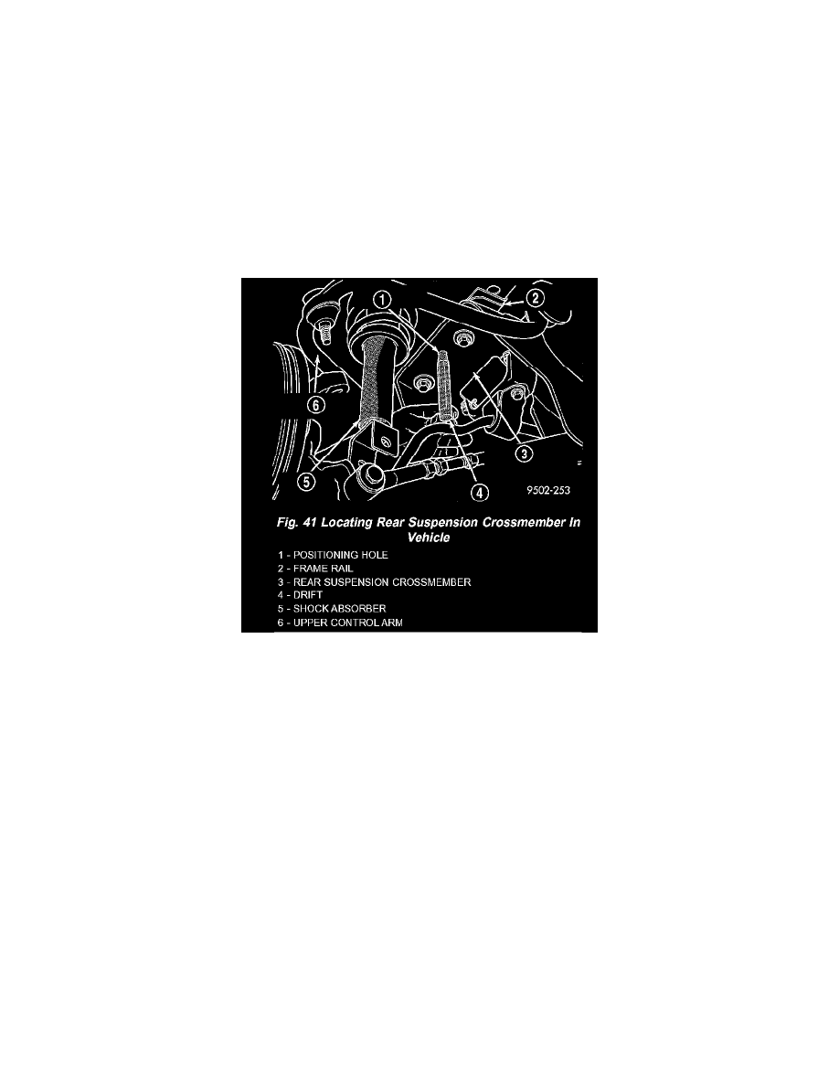
3. Position an appropriate size drift into the positioning hole in each side of rear suspension crossmember and crossmember locating holes in frame
rails of the vehicle. This is required to properly position rear suspension crossmember to the body of the vehicle. Tighten the 4 crossmember to
frame rail attaching bolts to 108 Nm (80 ft. lbs.). Remove drifts from rear suspension crossmember.
4. Remove transmission jack supporting rear suspension crossmember.
5. Install upper ball joint stud in knuckle. Install and tighten the ball joint stud nut to a torque of 27 Nm (20 ft. lbs.).
6. Install the brake tubing above the rear suspension crossmember into the routing clips on top of the crossmember.
Install rear brake calipers onto rear knuckles.
7. If vehicle is equipped with antilock brakes, attach wheel speed sensor heads to both rear knuckles. Tighten sensor mounting bolts to a torque of 8
Nm (75 inch lbs.).
8. If vehicle is equipped with antilock brakes, install routing clips for wheel speed sensor cables onto brackets on both upper control arms. Securely
tighten routing clip attaching bolts.
9. Install muffler support bracket on rear frame rail.
10. Install rear exhaust pipe hanger on rear suspension crossmember.
11. Install the shock absorber clevis brackets on the rear knuckles. Tighten the shock absorber mounting bolts to a torque of 95 Nm (70 ft. lbs.).
12. Install wheel and tire assembly on vehicle. Progressively tighten the wheel mounting nuts in crisscross sequence until all nuts are torqued to half
specification. Then repeat the tightening sequence to the full specified torque of 135 Nm (100 ft. lbs.).
13. Lower vehicle.
14. Check and reset if required, rear wheel Camber and Toe to preferred specifications.