
Town & Country Van V6-201 3.3L VIN R SMFI (1990)
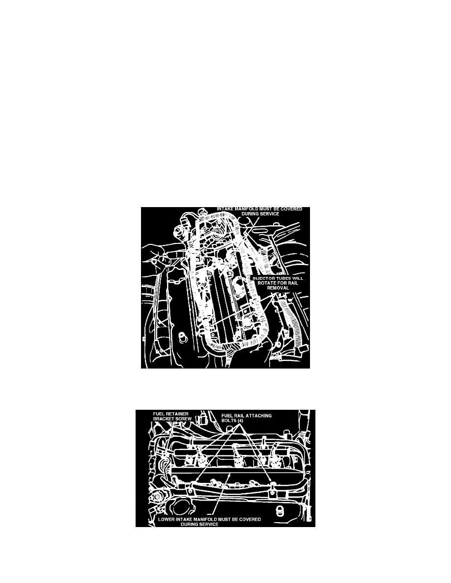
Figure 13 - Removing and Installing Valve Spring
Replace Valve Springs, Cylinder Head Not Removed
(1)
Remove valve covers and valve cover gaskets. Remove spark plugs.
(2)
Using suitable socket and flex handle at crankshaft pulley retaining screw, turn engine so the number 1 piston is at Top Dead Center on the
compression stroke.
(3)
Remove rocker arms with rocker shafts and install dummy shafts. (The rocker arms should not be disturbed and left on shafts.)
(4)
With air hose attached to cylinder air pressure adapter tool installed in number 1 spark plug hole, apply 90 to 100 psi air pressure (620.5 to 689
kPa), to hold valves in place when springs are removed.
(5)
Using Tool C-4682 (Fig. 13) compress valve spring only enough to remove retainer valve locks.
CAUTION: Do not pinch seal between retainer and top of guide. Remove valve spring and inspect valve seal for proper seating and possible damage.
Install new spring. Reinstall the valve retainer locks. Compress the spring only enough to install the locks. Remove adapter tool. Replace
other valve spring on number 1 cylinder in same way.
(6)
Follow the same procedure on the remaining 5 cylinders using the firing sequence 1-2-3-4-5-6. Make sure piston in cylinder is at TDC on the valve
spring that is being removed.
(7)
Remove dummy shafts and install rocker shafts with rocker arms and torque screws to 28 N-m (250 in.lbs.)
(8)
Install valve covers using new gaskets and torque screws to 14 N-m (120 in.lbs.).
Installation
(1)
Reinstall spark plugs and torque to 30 ft.lbs. (41 N-m).
(2)
Make sure the injector holes are clean and all plugs have been removed. Replace O-rings if damaged.
(3)
Lube injector O-ring with a drop of clean engine oil to ease installation.
Figure 12 - Fuel Rail Removal
(4)
Reinstall fuel rail. Put the tip of each injector into its port. Push the assembly into place until the injectors are seated in the ports (Fig. 12).
Figure 9 - Fuel Rail Attaching Bolts
(5)
Install the (4) fuel rail attaching bolts and torque to 22 N-m (200 in.lbs.) (Fig. 9).