
Avenger V6-2.7L Flex Fuel (2009)
Splice diagrams in Section 8W-70 show the entire splice and provide references to other sections the splices serves. Section 8W-70 only contains splice
diagrams that are not shown in their entirety somewhere else in the wiring diagrams.
Section 8W-80 shows each connector and the circuits involved with that connector. The connectors are identified using the name/number on the diagram
pages.
Removal
REMOVAL
1. Disconnect battery.
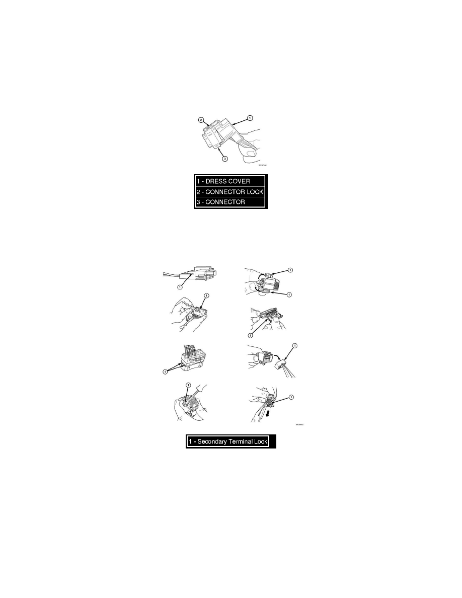
2. Release Connector Lock (2).
3. Disconnect the connector (3) being repaired from its mating half/component.
4. Remove the dress cover (if applicable) (1).
5. Release the Secondary Terminal Lock, if required (1).