
Caliber L4-2.4L (2009)
Crankshaft Position Sensor: Description and Operation
Operation
OPERATION
The PCM sends approximately 5 volts to the Hall-effect sensor. This voltage is required to operate the Hall-effect chip and the electronics inside the
sensor. A ground for the sensor is provided through the sensor return circuit. The input to the PCM occurs on a 5 volt output reference circuit that
operates as follows: The Hall-effect sensor contains a powerful magnet. As the magnetic field passes over the dense portion of the counterweight, the
5-volt signal is pulled to ground (0.3 volts) through a transistor in the sensor. When the magnetic field passes over the notches in the crankshaft
counterweight, the magnetic field turns off the transistor in the sensor, causing the PCM to register the 5-volt signal. The PCM identifies crankshaft
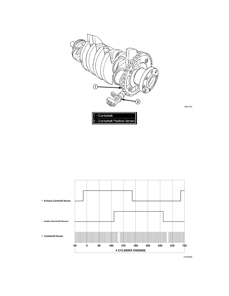
position by registering the change from 5 to 0 volts, as signaled from the Crankshaft Position sensor (2).
The PCM determines which cylinder to fire from the crankshaft position sensor input and the camshaft position sensor input. The #8 crankshaft
counterweight has a target ring with 32 teeth and notches (1), including one long reference tooth and notch. From the crankshaft position sensor input the
PCM determines engine speed and crankshaft angle (position).
NOTE: The graphic represents the relationship between camshaft and crankshaft sensors edges with camshafts in "lock pin" position (cam
shafts are not "phasing"). This is normally seen during idle.
Depiction of good camshaft and crankshaft square wave signals for 4 cylinder engines.