
Neon R/T L4-2.0L VIN F HO (2001)
Controller Antilock Brake: Description and Operation
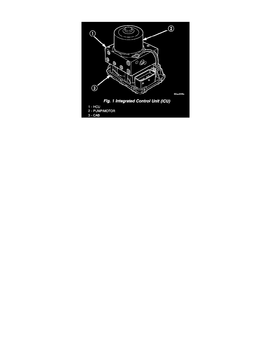
Fig.1 Integrated Control Unit (ICU)
CONTROLLER ANTILOCK BRAKE
The controller antilock brake (CAB) is a microprocessor-based device which monitors the ABS system during normal braking and controls it
when the vehicle is in an ABS stop. The CAB is mounted to the bottom of the HCU. The CAB uses a 25-way electrical connector on the vehicle
wiring harness. The power source for the CAB is through the ignition switch in the RUN or ON position. The CAB is on the PCI bus.
The primary functions of the controller antilock brake (CAB) are to:
-
monitor the antilock brake system for proper operation.
-
detect wheel locking or wheel slipping tendencies by monitoring the speed of all four wheels of the vehicle.
-
control fluid modulation to the wheel brakes while the system is in an ABS mode or the traction control system is activated.
-
store diagnostic information.
-
provide communication to the DRBIII scan tool while in diagnostic mode.
The CAB constantly monitors the antilock brake system for proper operation. If the CAB detects a fault, it will send a message to the Mechanical
Instrument Cluster (MIC) instructing it to turn ON the amber ABS warning indicator lamp and disable the antilock braking system. The normal
base braking system will remain operational.
The CAB continuously monitors the speed of each wheel through the signals generated by the wheel speed sensors to determine if any wheel is
beginning to lock. When a wheel locking tendency is detected, the CAB commands the CAB command coils to actuate. The CAB command coils
then open and close the valves in the HCU that modulate brake fluid pressure in some or all of the hydraulic circuits. The CAB continues to
control pressure in individual hydraulic circuits until a locking tendency is no longer present.
The CAB contains a self-diagnostic program that monitors the antilock brake system for system faults. When a fault is detected, the amber ABS
warning lamp is turned ON and the fault diagnostic trouble code (DTC) is then stored in a diagnostic program memory. These DTC's will remain
in the CAB memory even after the ignition has been turned OFF. The DTC's can be read and cleared from the CAB memory by a technician using
the DRB scan tool. If not cleared with a DRB scan tool, the fault occurrence and DTC will be automatically cleared from the CAB memory after
the identical fault has not been seen during the next 3,500 miles of vehicle operation.
Controller Antilock Brake Inputs
-
Wheel Speed sensors (four)
-
Brake Lamp switch
-
Ignition Switch
-
System Relay Voltage
-
Ground
-
Traction Control Lamp Actuation
-
Diagnostic Communication (PCI)
Controller Antilock Brake Outputs
-
Amber ABS warning indicator lamp actuation (through MIC)
-
Red BRAKE warning indicator lamp actuation (through MIC)
-
Traction control lamp
-
Diagnostic communication. (PCI)