
RAM 2500 Truck 2WD L6-5.9L DSL Turbo VIN 7 (2001)
Battery Tray: Service and Repair
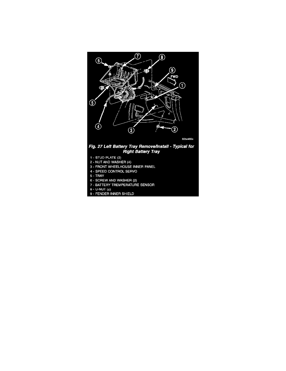
Battery Tray
REMOVAL
1. Remove the battery from the battery tray. Refer to Battery for the location of the proper battery removal procedure.
2. If the left battery tray is being removed, remove the battery temperature sensor from the left battery tray. Refer to Battery Temperature Sensor for
the location of the proper battery temperature sensor removal procedures.
Fig.27 Left Battery Tray Remove/Install - Typical For Right Battery Tray
3. Remove the two screws with washers that secure the outboard side of the battery tray to the inner fender shield (Fig. 27).
4. From the engine compartment, remove the two nuts with washers that secure the rear of the battery tray support to the two studs that extend
through the top of the front wheelhouse inner panel.
5. From inside the front fender wheelhouse, remove the two nuts with washers that secure the front of the battery tray support to the two studs that
extend through the underside of the front wheelhouse inner panel.
6. From inside the front fender wheelhouse, remove the stud plate that secures the rear of the battery tray support from the underside of the front
wheelhouse inner panel.
7. From the engine compartment, remove the battery tray and the stud plate that secures the front of the battery tray support from the front
wheelhouse inner panel as a unit.
8. If the vehicle is equipped with the optional vehicle speed control package, the speed control servo must be removed from the left battery tray
support to complete battery tray removal. Refer to Speed Control Servo for the location of the proper speed control servo removal procedures.
INSTALLATION
1. Clean and inspect the battery tray. Refer to Battery System for the location of the proper battery tray cleaning and inspection procedures.
2. If the vehicle is equipped with the optional vehicle speed control package, the speed control servo must be installed onto the left battery tray
support to complete battery tray installation. Refer to Speed Control Servo for the location of the proper speed control servo installation
procedures.
3. Install the stud plate onto the front of the battery tray support.
4. From the engine compartment, position the battery tray and the stud plate that secures the front of the battery tray support onto the front
wheelhouse inner panel as a unit.
5. From inside the front fender wheelhouse, loosely install the two nuts with washers that secure the front of the battery tray support to the two studs
that extend through the underside of the front wheelhouse inner panel.
6. From inside the front fender wheelhouse, position the stud plate that secures the rear of the battery tray support onto the underside of the front
wheelhouse inner panel.
7. From the engine compartment, loosely install the two nuts with washers that secure the rear of the battery tray support to the two studs that extend
through the top of the front wheelhouse inner panel.
8. Install and tighten the two screws with washers that secure the outboard side of the battery tray to the inner fender shield. Tighten the screws to