
RAM 3500 HD Truck 4WD L6-6.7L DSL Turbo VIN A (2007)
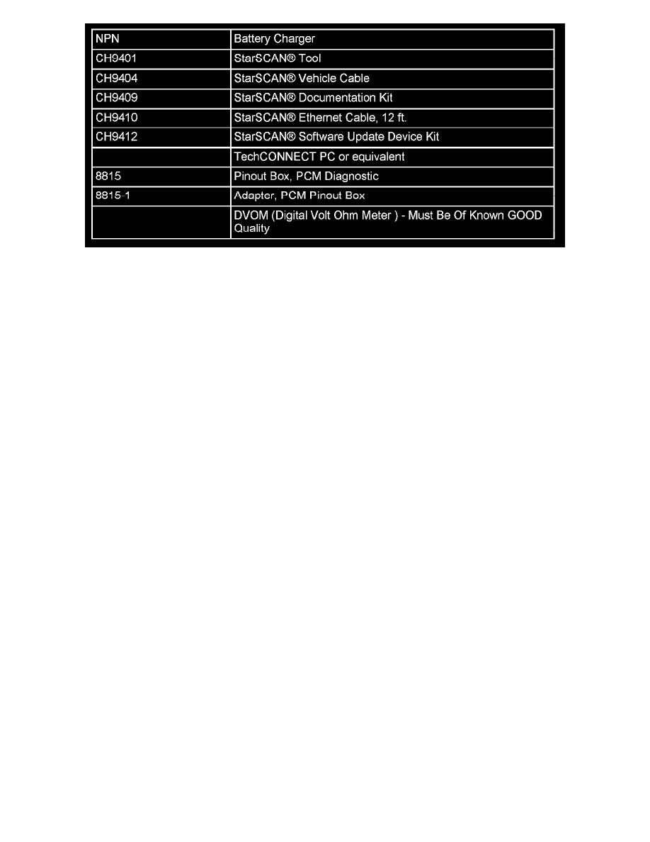
SPECIAL TOOLS / EQUIPMENT REQUIRED:
REPAIR PROCEDURE:
SECTION A - TCM CIRCUIT CHECK:
1.
Turn the ignition switch to the ** "LOCK" ** position and remove the ignition key from the ignition switch.
2.
Disconnect and isolate the negative battery cable from the battery negative terminal.
3.
Locate the TCM in the rear of the engine compartment.
4.
Disconnect the "D" (green) electrical harness connector from the TCM. The "D" connector will have a green color stripe to identify it.
5.
Install special tool 8815-1 (Adapter) to the TCM "D" connector. Connect the harness "D" connector to the 8815-1 Adapter.
6.
Install special tool 8815 (PCM Diagnostic Pinout Box) to the 8815-1 Adapter.
7.
Connect the negative battery cable to the battery.
8.
Turn the ignition switch to the ** "OFF" ** position (the first detent clockwise from the ** "LOCK" ** position). DO NOT turn the ignition
switch to the "ON/RUN" position, this will cause an incorrect voltage reading to be obtain when testing.
NOTE:
Verify that the ignition switch is in the ** "OFF" ** position and NOT in the "ON/RUN" position. The following steps must be followed in order.
9.
Check of the D19 circuit:
a.
Set the DVOM to DC voltage. Adjust the DC volts to the appropriate setting to correctly read 12 volts.
b.
Install the two leads of a known GOOD DVOM (Digital Volt Ohm Meter) to pins 13 and 19 of the 8815 Pinout Box. Install the negative
lead of the DVOM in pin 13, and the positive lead of the DVOM in pin 19.
c.
Pins 13 and 19 of the 8815 Pinout Box should connect to D13 (0 volts - ground) and to pins D19 (12 volts - switched battery voltage) of the
TCM.
d.
Does the VOLT meter read 12 volts?
e.
If YES, then proceed to the next step.
f.
If NO, then further diagnosis of the circuit is required.
10.
Check for a voltage difference between circuit D11 and D19:
a.
Install the two leads of a known GOOD DVOM (Digital Volt Ohm Meter) to pins 11 and 19 of the 8815 Pinout Box. Install the negative
lead of the DVOM in pin 11, and the positive lead of the DVOM in pin 19.