SRT-4 L4-2.4L Turbo VIN S (2004)

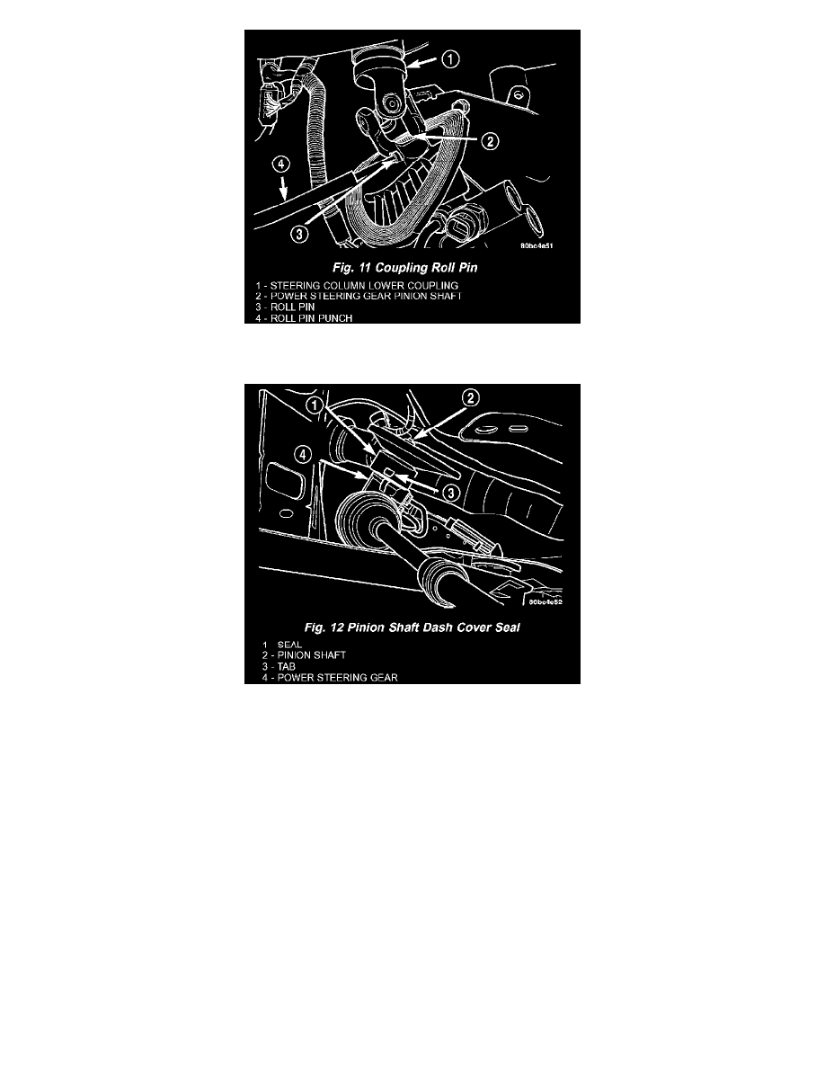
21. Remove the roll pin securing the steering column lower coupling to the power steering gear pinion shaft using a roll pin punch (Fig. 11). Push the
steering column lower coupling up and off of the power steering gear pinion shaft.
22. Release the pinion shaft dash cover seal from the tabs cast into the power steering gear housing and remove the seal from the power steering gear
(Fig. 12).
23. Loosen and remove the four bolts attaching the power steering gear to the front suspension crossmember (Fig. 1). Remove the power steering gear
from the front suspension crossmember.
REMOVAL - RHD
Right-Hand-Drive power steering gear is typical of Left-Hand-Drive.
INSTALLATION - POWER STEERING GEAR
1. Install the steering gear on the front suspension crossmember (Fig. 1). Install the four power steering gear mounting bolts. Tighten the mounting
bolts to a torque of 61 Nm (45 ft. lbs.).
2. Install the pinion shaft dash cover seal over the power steering pinion shaft and onto the power steering gear housing. Align the holes on each side
of the seal with the tabs cast into the power steering gear housing (Fig. 12).
3. With the steering column lower coupling pushed partway up through its hole in the dash panel, match the flat on the inside of the steering column
lower coupling to the flat on the power steering gear pinion shaft and slide the coupling onto the top of the pinion shaft. Align the roll pin hole in
the coupling with the groove in the pinion shaft and install the roll pin through the coupling until it is centered (Fig. 11).
4. Center the power steering gear rack in its travel.
5. Using the transmission jack, raise the front suspension crossmember and power steering gear until the crossmember contacts its mounting spot
against the body and frame rails of the vehicle. As the crossmember is raised, carefully guide the steering column lower coupling up through its
hole in the dash panel.
6. Start the two rear crossmember mounting bolts into the tapping plates mounted in the body. The right side bolt can be viewed in the mounting bolt
figure (Fig. 9). The left side bolt is located in the same location on the other side of the vehicle. Next, install the two front mounting bolts attaching
