
Stealth R/T Turbo V6-2972cc 3.0L DOHC Turbo (1996)
3. Insert tip of screwdriver [1.4 mm (0.06 in.) width] into connector in a manner as shown in the figure, raise housing lance slightly with it and pull
out harness.
CAUTION: Tool No. 753787-1 supplied by AMP can be used instead of screwdriver.
Computer Connector
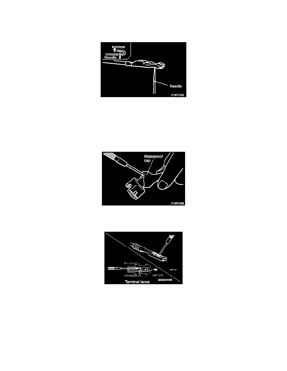
4. Insert needle through a hole provided on terminal and raise contact point of male terminal.
Injector Connector
Foreword
Connectors which are loose shall be rectified by removing the female terminal from connector housing and raising its lance to establish a more secure
engagement. Removal of connector terminal used for MFI and 4 A/T control circuit shall be done in the following manner:
Injector Connector
1. Remove waterproof cap.
Injector Connector
2. Insert tip of screwdriver [1.4 mm (0.06 in.) width] into connector in a manner as shown in the figure, press in terminal lance and pull out harness.
3. Press contact point of male terminal down by holding a screwdriver [1.4 mm (0.06 in.) width] in a manner as shown in the figure.
CAUTION: Correct lance to be in proper condition before terminal is inserted into connector.
Rectangular Waterproof Connector
Foreword
Connectors which are loose shall be rectified by removing the female terminal from connector housing and raising its lance to establish a more secure
engagement. Removal of connector terminal used for MFI and 4 A/T control circuit shall be done in the following manner: