
Medallion L4-2165cc 2.2L (1988)
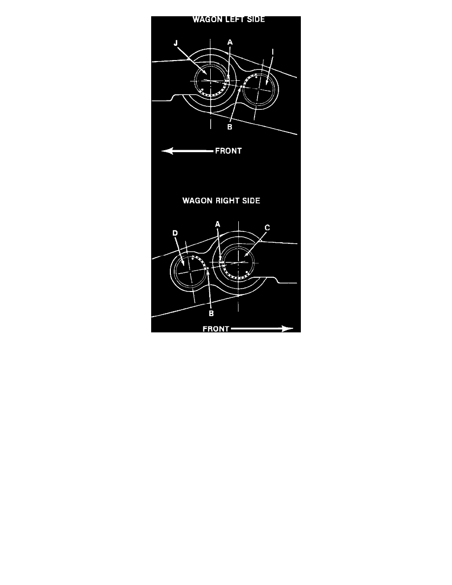
Fig. 15 Positioning anti-sway & suspension bars (torsion bar installation all four bars). Wagon models
4. On wagon models, proceed as follows:
a. The anti-sway (stabilizer) bars (D and I) are positioned 5 teeth up from the mark (B) made previously.
b. The suspension bars (J and C) are positioned 10 teeth down from the initial position mark (A).
5. With anti-sway and suspension bars properly positioned, slide anti-sway (stabilizer) bar through the mounting hole.
6. Position bar into mounting hole as described previously.
7. Slip torsion bar connecting link over the two previously installed torsion bars. The connecting link must fit into the V shaped section of the
rear axle assembly.
8. Slide suspension bar through mounting hole.
9. Position bar into mounting hole as described previously.
10. Slide anti-sway (stabilizer) bar through mounting hole, then position bar into hole as described previously and slide into connecting link. If it is
difficult to align the torsion bars, the connecting link can be slightly twisted to facilitate alignment of the torsion bars.
11. Remove threaded rod tool assembly, install wheels, lower vehicle and check vehicle ride height.
12. Adjust vehicle ride height, if necessary.