
Vision V6-3.5L VIN F (1997)
Hydraulic Control Assembly - Antilock Brakes: Service and Repair
Installation
PROCEDURE
1.
Install the HCU back in its mounting bracket using the reverse sequence of removing it from bracket. Install and securely tighten the 3 HCU
mounting isolator to bracket mounting nuts.
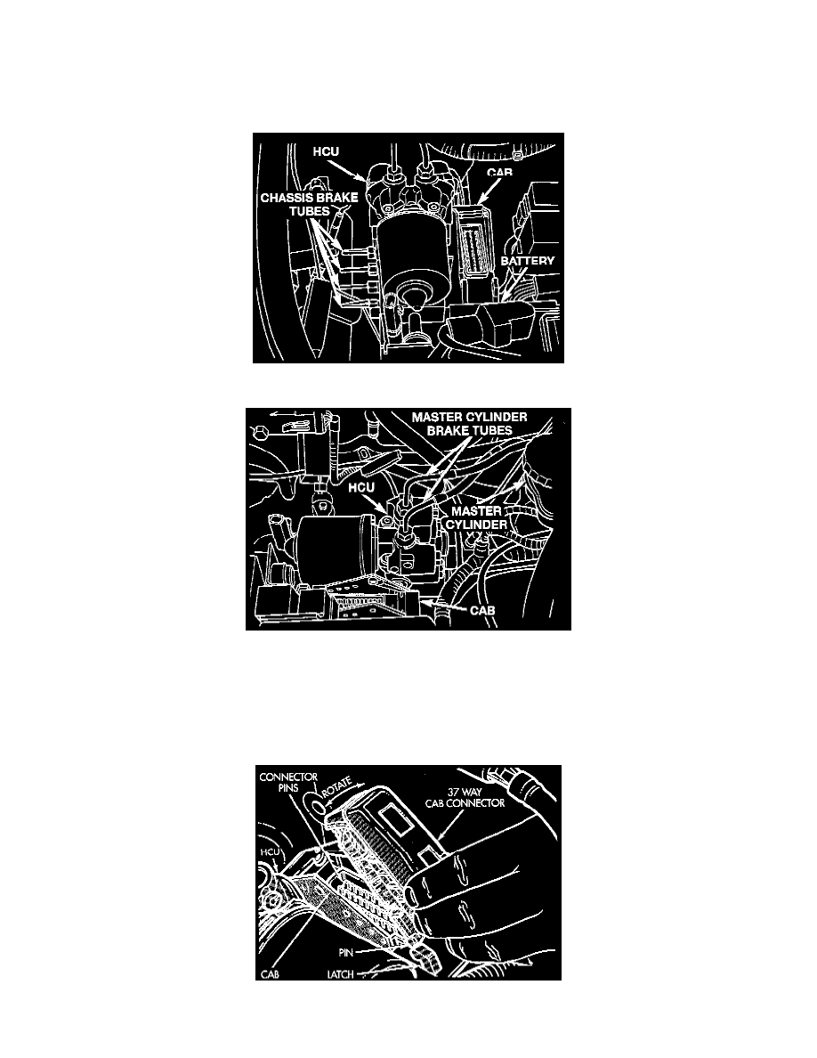
Brake Tube Connections At HCU
Master Cylinder Brake Tube Connections At HCU
2.
Connect the 2 brake fluid supply tubes from the master cylinder onto the inlet ports of the Hydraulic Control Unit HCU. Connect the 4 brake
fluid output tubes to the ports on the HCU. Torque all brake tube fitting nuts to 19 Nm (14 ft. lbs.).
CAUTION: Verify that the vehicle's ignition switch is in the off position before connecting the 60 way connector on the Controller Antilock
Brake CAB.
Connector Removal From CAB