
Vision V6-3.5L VIN F (1997)
Hydraulic Control Assembly - Antilock Brakes: Description and Operation
CAUTION: THE ONLY PART OF THE HYDRAULIC CONTROL UNIT HCU THAT IS REPLACEABLE IS THE MOUNTING
BRACKET. THE REMAINING COMPONENTS OF THE HCU ARE NOT SERVICEABLE OR REPLACEABLE ITEMS. NO ATTEMPT
SHOULD EVER BE MADE TO REMOVE OR SERVICE ANY OTHER PARTS OF THE HCU.
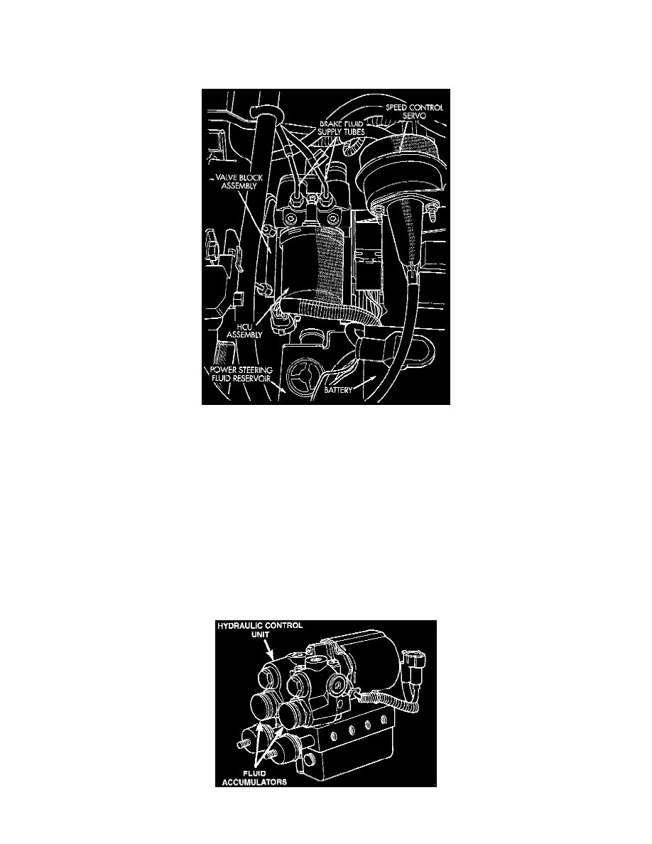
Teves Mark IV-G ABS HCU Mounting Location
GENERAL INFORMATION
The Hydraulic Control Unit HCU is located in the engine compartment on the left frame rail forward of the master cylinder and is covered by a
heat shield. The HCU contains the valve block assembly, the pump/motor assembly, and fluid accumulators.
HCU VALVE BLOCK
The valve block assembly on a vehicle which is equipped only with ABS contains eight valve/solenoids: four inlet valves and four outlet valves.
The valve block assembly on a vehicle which is equipped with ABS and traction control contains ten valve/solenoids: four inlet valves four outlet
valves and 2 additional valves for the traction control function. The inlet valves are spring loaded in the open position and the outlet valves are
spring loaded in the closed position. During an antilock stop these valves are cycled to maintain the proper slip ratio for each channel. If a wheel
locks, the inlet valve is closed to prevent any further pressure increase. Then the outlet valve is opened to release the pressure back to the
accumulators until the wheel is no longer slipping. Once the wheel is no longer slipping the outlet valve is closed and the inlet valve is opened to
reapply pressure. If the wheel is decelerating within its predetermined limits (proper slip ratio), both valves will close to hold the pressure constant.
During the stop, the build pressure is initially supplied by the master cylinder. During decay, the fluid is dumped to the fluid accumulators by the
pump and restored to high pressure for the next build cycle.
HCU Fluid Accumulators