| In-vehicle Repair Special Tool(s) | | Separator, Ball Joint 211-020 (13006) | Removal | | -
Disconnect the battery ground cable. | | | -
Disconnect the upper heated oxygen sensor (HO2S) electrical connector. | | | -
Remove the exhaust gas recirculation (EGR) valve from the intake manifold. | | | -
Loosen the RH front wheel nuts. | | | -
Remove the RH front wheel. | | | -
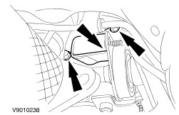
Remove the RH fender splash shields. | | | -
Loosen the accessory drive belt and remove the drive belt from the generator. | | | -
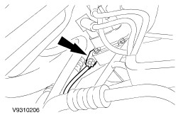
Using the special tool, disconnect the tie-rod end (LH-side shown). | | | -
Disconnect the lower HO2S electrical connector. | | | -
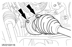
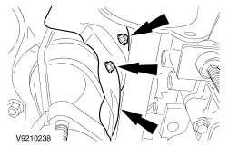
Remove the front axle drive halfshaft center bearing bolts and the heat shield. | | | -
Remove the front axle drive halfshaft center bearing bracket. | | | -
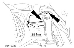
Remove the upper HO2S sensor and the EGR pipe. | | | -
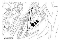
Remove the exhaust manifold heat shield. | | | -
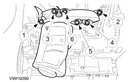
Remove the exhaust manifold (shown on removed engine). | Installation | | -
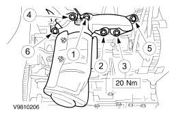
NOTE:Tighten the nuts in the sequence shown. Install the exhaust manifold with a new gasket (shown on removed engine). | | | -
Install the exhaust manifold heat shield. | | | -
Position the EGR pipe to exhaust manifold. | | | -
Install the EGR valve to intake manifold. | | | -
Install the upper HO2S and tighten the EGR pipe. | | | -
Install the front axle drive halfshaft center bearing bracket. | | | -
Install the front axle drive halfshaft center bearing bolts and the heat shield. | | | -
Install the exhaust pipe. | | | -
Connect the lower HO2S electrical connector. | | | -
Install the tie-rod end (LH-side shown). | | | -
Install the accessory drive belt to the generator. | | | -
Install the lower fender splash shields. | | | -
Install the RH front wheel. | | | -
Connect the upper HO2S electrical connector. | | | -
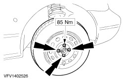
Tighten the front wheel nuts. | | | -
NOTE:When the battery has been disconnected and reconnected, some abnormal drive symptoms may occur while the vehicle relearns its adaptive strategy. The vehicle may need to be driven 16 km (10 miles) or more to relearn the strategy. Connect the battery ground cable. | | |