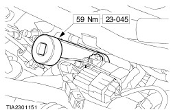
| Description and Operation Introduction This manual has been written in a format that is designed to meet the needs of Ford technicians worldwide. The objective is to use common formats and include similar content in each manual worldwide. This manual provides general descriptions for accomplishing service and repair work with tested, effective techniques. Following them will help maintain reliability. Replacement Parts Ford and Motorcraft products are replacement parts made to the same exacting standards as the original factory fitted components. For this reason, it is recommended that only genuine Ford or Motorcraft parts are used as service replacements. Special Tools The Special Service Tool chart given at the start of each procedure shows all European sourced tools necessary to carry out a repair. When possible, illustrations are given to assist in identifying the tool needed. Special Tools may be ordered from OTC Europe or their agents/distributors. Loewener OTC GmbH Industriestrasse 67 D40764 Langenfeld Germany Tel: +49 (0) 2173 928-0 Fax: +49 (0) 2173 928-199 Important Safety Instructions Appropriate service methods and correct repair procedures are essential for the safe, reliable operation of all motor vehicles as well as the personal safety of the individual doing the work. This manual cannot possibly anticipate all such variations and provide advice or cautions as to each. Anyone who departs from the instructions provided in this manual must first establish that neither personal safety nor vehicle integrity is compromised by their choice of methods, tools or parts. Warnings, Cautions and Notes in This Manual WARNING:Warnings indicate when failure to follow a procedure correctly or ignoring the warning instructions may cause personal injury. CAUTION:Cautions indicate when failure to follow a procedure correctly may cause damage to the vehicle or component. NOTE:To amplify or provide supplementary information relevant to a procedure or descriptive text. As you read through this manual, you will come across WARNINGS, CAUTIONS and NOTES. A warning, caution or note is placed at the beginning of a series of steps if it applies to multiple steps. If the warning, caution or note only applies to one step, it is placed at the beginning of the specific step (after the step number). How to Use This Manual This Workshop Manual covers service and repair procedures and maintenance This manual is structured into groups and sections, with specific system sections collected together under their relevant group. A group covers a specific portion of the vehicle. The manual is divided into five groups, General Information, Chassis, Powertrain, Electrical and Body and Paint. The number of the group is the first number of a section number. Pages at the start of the manual list all sections available. Each section has a contents list detailing General Specifications, Description and Operation and Service Procedures and Checks. If components need to be removed or dismantled in sequence they will be identified numerically in an illustration and the corresponding text will be numbered accordingly (refer to `Samples'). All left and right-hand references to the vehicle are taken from a position sitting in the drivers seat looking forward. All left and right-hand references to the engine are taken from a position at the flywheel looking towards the front camshaft pulley. Where appropriate, instructions will be given for the use of either FDS2000 or New Generation STAR testing equipment. Inspection and Verification Visual inspection charts, symptom charts and other information charts (such as diagnostic routines), supplement test procedures with technical specifications, or navigate the technician to a specific test procedure. Sympton Chart The symptom chart indicates symptoms, sources and actions to address a condition. Pinpoint Tests For electrical systems, pinpoint test steps are used to identify the source of a concern in a logical, step-by-step manner. Pinpoint tests have two columns: CONDITIONS and DETAILS/RESULTS/ACTIONS. The CONDITIONS column is used exclusively for graphics and icons (with or without captions) and DETAILS/RESULTS/ACTIONS column gives the technician direction to another test step or specific corrective actions as a result of the test performed. The boxed numbers indicate the order in which the described action is to be performed. Component Tests A component test is used when a component is tested in multiple pinpoint tests, or if a procedure is too complicated to be formatted within a single page of the pinpoint test. Graphics Test graphics show the measurement or test to be performed in a test step. A representative tester graphic is used for voltmeters and ohmmeters. If multiple measurements are made in a single graphic, the test leads are drawn with a solid line until the test lead splits to indicate the multiple measurements, at which point dashed lines are used. Breakout box-type testers are represented by a double circle test pin. Test pins are labelled with the pin number. Samples Special Tools and Torque Figures Any requirement for special tools will picture the tool, showing it in use and with its tool number shown. Torque settings will be given at the relevant point in the procedure. |