| PINPOINT TEST B : THE HORN DOES NOT SOUND |
| TEST CONDITIONS | DETAILS/RESULTS/ACTIONS |
| B1: CHECK THE HORN RELAY |
| | 1 Disconnect Horn Relay C69. |
| | 2 Carry out the relay component test. REFER to Component Test in this section. |
| | Is the relay OK? Yes No INSTALL a new horn relay. TEST the system for normal operation. |
| B2: CHECK POWER TO THE HORN |
| | 1 Connect Horn Relay C69. |
| | 2 Disconnect Horn C981. |
| | 3 Measure voltage between horn C981 pin 1, circuit 30S-GJ6 (RD/YE) harness side and ground when the horn is in the ON position. |
| | Is the voltage greater than 10 volts? Yes INSTALL a new horn. TEST the system for normal operation. No |
| B3: CHECK THE HORN CIRCUIT |
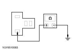
| | 1 Measure the resistance between BJB pin 5, circuit 30S-GJ6 (RD/YE) component side and the horn C981 pin 1, circuit 30S-GJ6 (RD/YE) harness side. |
| | Is the resistance less than 5 ohms? Yes No REPAIR circuit 30S-GJ6 (OG/YE). TEST the system for normal operation. |
| B4: CHECK POWER TO HORN SWITCH |
| | 1 |
| | 2 Disconnect Air Bag Sliding Contact C896. |
| | 3 Measure the resistance between the air bag sliding contact C896 pin 2, circuit 31S-GJ7 (BK/BU) harness side and ground with the horn in the ON position. |
| | Is the resistance less than 5 ohms? Yes No |
| B5: CHECK CIRCUIT 31S-GJ7 FOR OPEN |
| | 1 Disconnect Horn Relay C69. |
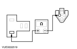
| | 2 Measure the resistance between the air bag sliding contact C896 pin 2, circuit 31S-GJ7 (BK/BU) harness side and BJB 31S-GJ7 (BK/BU) component side. |
| | Is the resistance less than 5 ohms? Yes INSTALL a new BJB. TEST the system for normal operation. No REPAIR circuit 31S-GJ7 (BK/BU). TEST the system for normal operation. |
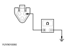
| B6: CHECK AIR BAG SLIDING CONTACT |
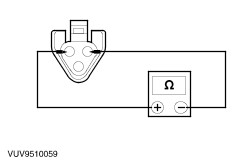
| | 1 Measure the resistance between air bag sliding contact C896 pin 1, and pin 2, component side with the horn in the ON position. |
| | Is the resistance less than 5 ohms? Yes No |
| B7: CHECK THE HORN SWITCH GROUND CIRCUIT |
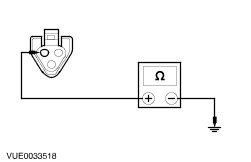
| | 1 Measure the resistance between the air bag sliding contact C896 pin 1, circuit 31-PG13 (BK) harness side and ground. |
| | Is the resistance less than 5 ohms? Yes INSTALL a new BJB. TEST the system for normal operation. No For vehicles equipped with speed control, GO to B9. . For vehicles not equipped with speed control. REPAIR circuit 31-PG13 (BK). TEST the system for normal operation. |
| B8: CHECK THE HORN SWITCH |
| |
| | 1 |
| | 2 Disconnect Horn Switch N54 (Vehicles Without Speed Control) N78 (Vehicles With Speed Control). |
| | 3 Measure the resistance between horn switch pin B and pin C component side. Take a note of the reading with the switch pressed as well as with the switch released. |
| | Is the resistance greater than 10,000 ohms with the switch released and less than 5 ohms with the switch pressed? Yes INSTALL a new air bag sliding contact. TEST the system for normal operation. No INSTALL a new horn switch(es). REFER to Horn Switch in this section. TEST the system for normal operation. |
| B9: CHECK THE GROUND TO THE HORN SWITCH |
| | 1 Disconnect Speed Control Module C833. |
| | 2 Measure the resistance between the speed control module C833 pin 10, circuit 91-PG12 (BK/WH) harness side and ground. |
| | Is the resistance less than 5 ohms? Yes REPAIR circuit 31-PG13. TEST the system for normal operation. No REPAIR circuit 31-PG12. TEST the system for normal operation. |