| PINPOINT TEST C : A SINGLE MIRROR DOES NOT FUNCTION WITH SWITCH LOGIC |
| TEST CONDITIONS | DETAILS/RESULTS/ACTIONS |
| C1: CHECK THE EXTERIOR MIRROR CONTROL SWITCH |
| | 1 Disconnect Exterior Mirror Control Switch C740. |
| | 2 Carry out a component test of the exterior mirror control switch. For additional information, refer to the Wiring Diagrams. |
| | Is the switch OK? Yes Driver exterior mirror up/down. GO to C2. Driver exterior mirror left/right. GO to C5. Passenger exterior mirror up/down. GO to C8. Passenger exterior mirror left/right. GO to C11. No INSTALL a new exterior mirror. TEST the system for normal operation. |
| C2: CHECK THE DRIVER EXTERIOR MIRROR UP/DOWN CIRCUIT |
| | 1 Connect Exterior Mirror Control Switch C740. |
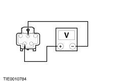
| | 2 Disconnect Driver Exterior Mirror C807. |
| | 3 Measure the voltage between the exterior mirror C807 pin 2, circuit 33-AD6 (YE), and pin 4, circuit 32-AD7 (WH/RD), harness side. - Operate the exterior mirror control switch UP and DOWN.
|
| | Is the voltage greater than 10 volts when the exterior mirror control switch is moved to the UP position and is the polarity reversed when moved to the DOWN position? Yes INSTALL a new exterior mirror. TEST the system for normal operation. No |
| C3: CHECK CIRCUIT 32-AD7 (WH/RD) FOR CONTINUITY |
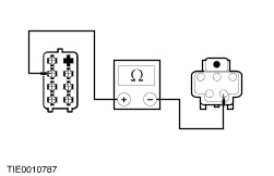
| | 1 Disconnect Exterior Mirror Control Switch C740. |
| | 2 Measure the resistance between the exterior mirror control switch C740 pin 2, circuit 32-AD7 (WH/RD), harness side, and the exterior mirror C807 pin 4, circuit 32-AD7 (WH/RD), harness side. |
| | Is the resistance less than 5 ohms? Yes No REPAIR circuit 32-AD7 (WH/RD). TEST the system for normal operation. |
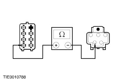
| C4: CHECK CIRCUIT 33-AD6 (YE) FOR CONTINUITY |
| | 1 Measure the resistance between the exterior mirror control switch C740 pin 3, circuit 33-AD1 (YE/RD), harness side, and the exterior mirror C807 pin 2, circuit 33-AD6 (YE), harness side. |
| | Is the resistance less than 5 ohms? Yes INSTALL a new exterior mirror. TEST the system for normal operation. No REPAIR circuit 33-AD6 (YE). TEST the system for normal operation. |
| C5: CHECK THE DRIVER EXTERIOR MIRROR LEFT/RIGHT CIRCUIT |
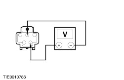
| | 1 Disconnect Driver Exterior Mirror C807. |
| | 2 Measure the voltage between the exterior mirror C807 pin 2, circuit 33-AD6 (YE), and pin 5, circuit 32-AD8 (WH/BU), harness side. - Operate the exterior mirror control switch LEFT and RIGHT.
|
| | Is the voltage greater than 10 volts when the exterior mirror control switch is moved to the LEFT position and is the polarity reversed when moved to the RIGHT position? Yes INSTALL a new exterior mirror. TEST the system for normal operation. No |
| C6: CHECK CIRCUIT 32-AD8 (WH/BU) FOR CONTINUITY |
| | 1 Disconnect Exterior Mirror Control Switch C740. |
| | 2 Measure the resistance between the exterior mirror control switch C740 pin 5, circuit 32-AD8 (WH/BU), harness side, and the exterior mirror C807 pin 5, circuit 32-AD8 (WH/BU), harness side. |
| | Is the resistance less than 5 ohms? Yes No REPAIR circuit 32-AD8 (WH/BU). TEST the system for normal operation. |
| C7: CHECK CIRCUIT 33-AD6 (YE) FOR CONTINUITY |
| | 1 Measure the resistance between the exterior mirror control switch C740 pin 3, circuit 33-AD1 (YE/RD), harness side, and the exterior mirror C807 pin 2, circuit 33-AD6 (YE), harness side. |
| | Is the resistance less than 5 ohms? Yes INSTALL a new exterior mirror. TEST the system for normal operation. No REPAIR circuit 33-AD6 (YE). TEST the system for normal operation. |
| C8: CHECK THE PASSENGER EXTERIOR MIRROR UP/DOWN CIRCUIT |
| | 1 Connect Exterior Mirror Control Switch C740. |
| | 2 Disconnect Passenger Exterior Mirror C71. |
| | 3 Measure the voltage between the exterior mirror C71 pin 2, circuit 33-AD20 (YE) and pin 4, circuit 32-AD22 (WH), harness side. - Operate the exterior mirror control switch UP and DOWN.
|
| | Is the voltage greater than 10 volts when the exterior mirror control switch is moved to the UP position and is the polarity reversed when moved to the DOWN position? Yes INSTALL a new exterior mirror. TEST the system for normal operation. No |
| C9: CHECK CIRCUIT 32-AD10 (WH/BK) OR 32-AD22 (WH) FOR CONTINUITY |
| | 1 Disconnect Exterior Mirror Control Switch C740. |
| | 2 Measure the resistance between the exterior mirror control switch C740 pin 1, circuit 32-AD10 (WH/BK), harness side, and C71 pin 4, circuit 32-AD22 (WH), harness side. |
| | Is the resistance less than 5 ohms? Yes No REPAIR circuit 32-AD10 (WH/BK) or 32-AD22 (WH). TEST the system for normal operation. |
| C10: CHECK CIRCUIT 33-AD20 (YE) FOR CONTINUITY |
| | 1 Measure the resistance between the exterior mirror control switch C740 pin 3, circuit 33-AD1 (YE/RD), harness side, and the exterior mirror C71 pin 2, circuit 33-AD20 (YE), harness side. |
| | Is the resistance less than 5 ohms? Yes INSTALL a new exterior mirror. TEST the system for normal operation. No REPAIR circuit 33-AD20 (YE). TEST the system for normal operation. |
| C11: CHECK THE PASSENGER EXTERIOR MIRROR LEFT/RIGHT CIRCUIT |
| | 1 Disconnect Passenger Exterior Mirror C71. |
| | 2 Measure the voltage between the exterior mirror C71 pin 2, circuit 33-AD20 (YE), harness side, and C71 pin 5, circuit 32-AD23 (WH/RD) harness side. - Operate the exterior mirror control switch LEFT and RIGHT.
|
| | Is the voltage greater than 10 volts when the exterior mirror control switch is moved to the LEFT position and is the polarity reversed when moved to the RIGHT position? Yes INSTALL a new exterior mirror. TEST the system for normal operation. No |
| C12: CHECK CIRCUIT 32-AD11 (WH/VT) FOR CONTINUITY |
| | 1 Disconnect Exterior Mirror Control Switch C740. |
| | 2 Measure the resistance between the exterior mirror control switch C740 pin 5, circuit 32-AD11 (WH/VT), harness side, and the exterior mirror C71 pin 5, circuit 32-AD23 (WH/RD), harness side. |
| | Is the resistance less than 5 ohms? Yes No REPAIR circuit 32-AD11 (WH/VT) or 32-AD23 (WH/RD). TEST the system for normal operation. |
| C13: CHECK CIRCUIT 33-AD20 (YE) FOR CONTINUITY |
| | 1 Measure the resistance between the exterior mirror control switch C740 pin 3, circuit 33-AD1 (YE/RD) harness side, and the exterior mirror C71 pin 2, circuit 33-AD20 (YE), harness side. |
| | Is the resistance less than 5 ohms? Yes INSTALL a new exterior mirror. TEST the system for normal operation. No REPAIR circuit 33-AD20 (YE). TEST the system for normal operation. |