
E 350 V10-6.8L (2007)
2. WARNING: Incorrect centralization may result in premature component failure. If in doubt when centralizing the clockspring, repeat
the centralizing procedure. Failure to follow this instruction may result in personal injury.
CAUTION: Make sure the road wheels are in the straight-ahead position.
If the vehicle's clockspring has rotated out of center, follow these steps to center the clockspring.
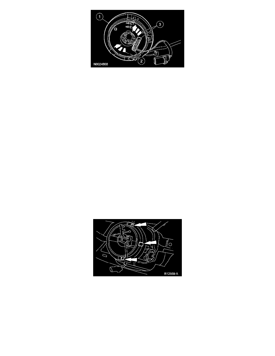
1
Hold the clockspring outer housing stationary.
2
CAUTION: Overturning will destroy the clockspring. The internal ribbon wire acts as the stop and can be broken from its internal
connection.
While turning the rotor clockwise, carefully feel for the ribbon wire to run out of length and for a slight resistance. Stop turning at this point.
3
Turn the clockspring counterclockwise approximately 2.25 turns. This is the center point of the clockspring.
-
Do not allow the rotor to turn from this position.
Vehicle repairs reusing the same clockspring
3. NOTE: When the tape is removed, do not allow the clockspring to turn.
Remove the tape applied during clockspring removal.
All vehicles
4. NOTE: Slight turning of the clockspring rotor is allowable for alignment purposes to the steering column.
With the flats of the clockspring rotor aligned to the flats of the steering column shaft, slide the clockspring onto the steering column engaging the
retaining tabs.
5. Press at the 6, 12 and 3 o`clock positions to seat the clockspring.
6. Route the clockspring wiring through the instrument panel.
7. Attach the 2 clockspring retaining clips holding the wire to the steering column.