
Explorer 2WD V6-245 4.0L SOHC VIN E EFI (1997)
6. Back out the servo gauge adjusting screw until it bottoms out on the tool. Record the distance the servo piston traveled.
NOTE: If the piston travel in this step is 3-5.6 mm (0.120-0.220 in), it is within specification. If the piston travel is greater than 5.6 mm (0.220
in), use the next longer piston and rod. If the piston travel is less than 3 mm (0.120 in), use the next shorter piston and rod.
7. Use the above procedure to check the piston travel with the newly selected low/reverse band servo piston and rod (if required) to make sure that
the piston travel is 3-5.6 mm (0.120-0.220 in). Remove the servo gauge and the low/reverse band servo return spring.
-
Grooves are located on low/reverse servo rod.
1 groove is 54/53 mm (2.112/2.085 inches) in length
No groove is 51/50 mm (2.014/1.986 inches) in length
2 grooves is 49/48 mm (1.915/1.888 inches) in length
CAUTION: Make sure the test spring is removed after this step.
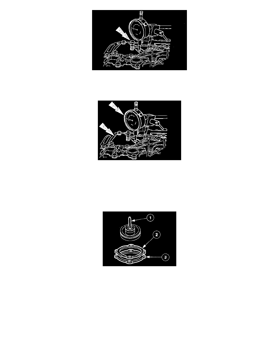
8. Install the selected low/reverse band servo piston and rod.
(1) Install the low/reverse band servo piston and rod assembly.
(2) Install a new low/reverse servo separator plate cover gasket.
(3) Install the low/reverse band servo cover.
-
Loosely install the low/reverse servo piston cover bolts.