
Explorer 2WD V8-4.6L VIN 8 (2006)
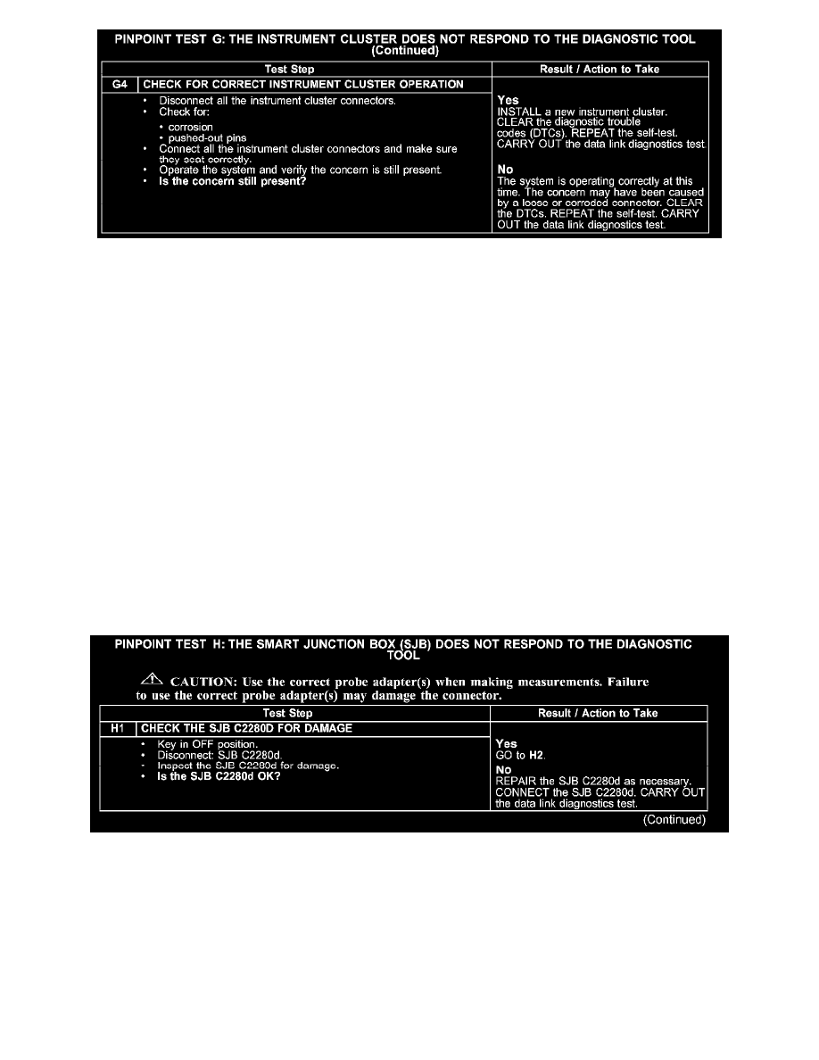
G4
Normal Operation
The instrument cluster communicates with the diagnostic tool and all the modules on the high speed controller area network (CAN) through circuits
VDB04 (WH/BU) and VDB05 (WH). The instrument cluster also communicates with other modules on the medium speed CAN circuits VDB06
(GY/OG) and VDB07 (VT/OG). The instrument cluster serves as a gateway between the medium speed CAN and the high speed CAN network
modules.
On the high speed CAN, the PCM and instrument cluster share network termination responsibilities with the use of a split termination resistor in each
module. On the medium speed CAN, the smart junction box (SJB) and instrument cluster share network termination responsibilities with the use of a
split termination resistor in each module.
The total resistance values must not be more than 5 ohms. If the resistance is more than 5 ohms there is an open in one of the high speed CAN
circuits, damage to the DLC C251, damage to the instrument cluster C220, or a problem in an in-line connector.
Possible Causes
-
high speed CAN data plus circuit VDB04 (WH/BU) open
-
high speed CAN data minus circuit VDB05 (WH) open
-
medium speed CAN data plus circuit VDB06 (GY/OG) open
-
medium speed CAN data minus circuit VDB07 (VT/OG) open
-
instrument cluster C220
-
instrument cluster
Test H: The Smart Junction Box (SJB) Does Not Respond To The Diagnostic Tool
PINPOINT TEST H: THE SMART JUNCTION BOX (SJB) DOES NOT RESPOND TO THE DIAGNOSTIC TOOL
H1