
Explorer 4WD V6-245 4.0L (1991)
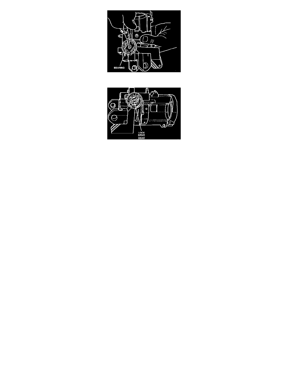
Fig. 6 Removing Ignition Lock Bearing
Fig. 7 Ignition Lock Drive Gear
LESS KEY
The following procedure applies to vehicles where the ignition lock is inoperative or lock cylinder cannot be rotated due to broken or missing
ignition key and the key number is unknown, or the lock cylinder cap is damaged and/or broken so that lock cylinder cannot be rotated.
Removal
1.
Disconnect battery ground cable, then remove steering wheel. Ensure steering wheel is in full up position on models with tilt steering.
2.
On models with tilt steering, remove tilt lever, then the steering column collar by pressing on collar from top and bottom while removing.
3.
On all models, remove lower dash panel trim cover, then the column shroud retaining screws from bottom of column shroud.
4.
Remove bottom half of shroud by pulling shroud down and toward rear of vehicle. Move shift lever as required to ease shroud removal on
models with automatic transmission.
5.
Lift top half of shroud from column.
6.
Punch lock cylinder retaining pin using a 1/8 inch maximum diameter prick punch, then drill out retaining pin using a 1/8 inch diameter drill, to a
depth of 1/2 inch maximum. Use care not to damage cast housing when drilling out retaining pin.
7.
Place a chisel at base of ignition lock cylinder cap, then strike chisel with sharp blows using a suitable hammer to break cap away from lock
cylinder.
8.
Using a 3/8 inch diameter drill, drill down middle of ignition lock key slot approximately 1 3/4 inch until lock cylinder breaks loose from steering
column cover casting, then remove lock cylinder and drill shavings from base of cover cast housing.
9.
Remove white plastic bearing retainer by inserting a suitable tool with a 90° bend on tip between bearing retainer and bearing and prying upward,
Fig. 5. Note position of bearing retainer prior to removal.
10.
Insert tip of a suitable screwdriver into double-D slot of bearing, Fig. 6, rotate 90°, then remove bearing.
11.
Remove lock drive gear, Fig. 7, noting relationship of lock drive gear to rack teeth.
Installation
1.
Lubricate and position lock drive gear in base of lock cylinder housing in same position as noted during removal. Position of lock drive gear is
correct if last tooth on drive gear is meshed with last groove on rack.
2.
Position bearing in lock cylinder housing, insert tip of screwdriver into double-D slot of bearing, then rotate bearing 90°.
3.
Press white plastic bearing retainer into lock cylinder housing, ensuring retainer is in original position, then press firmly to snap into place.
4.
Line up flats of drive gear with flats of washer by pulling down on column lock actuator. This will place actuator in RUN position.
5.
Lubricate lock cylinder with suitable grease, then turn lock cylinder to ON position and depress retaining pin.
6.
Insert lock cylinder into housing in flange casting, ensuring that tab at end of cylinder aligns with slot in ignition drive gear.
7.
Turn key to OFF position, allowing cylinder retaining pin to extend into cylinder casting housing hole.
8.
Rotate lock cylinder to all positions, ensuring cylinder is operating properly.
9.
Connect lock cylinder electrical connector to horn brush electrical connector.
10.
Position top half of steering column shroud onto column so that screw moldings on shroud seat in mounting bores in column. Place shift lever in
lowest position to aid assembly on vehicles with automatic transmission.