
F 150 4WD V8-4.6L VIN 8 (2010)
-
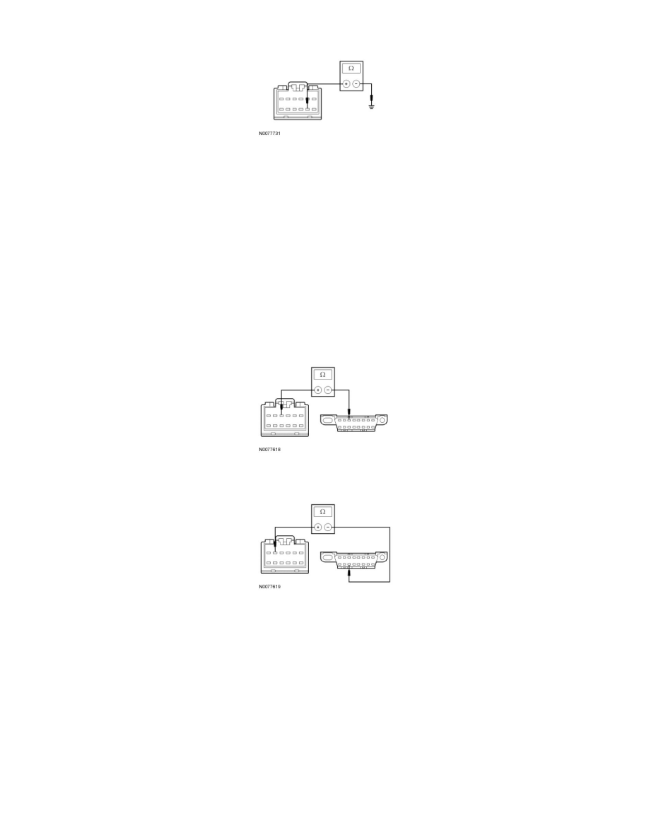
Measure the resistance between the FDIM C2123-8, circuit GD133 (BK), harness side and ground.
-
Is the resistance less than 5 ohms?
Yes
GO to N3.
No
REPAIR the circuit. CONNECT the negative battery cable. CLEAR the DTCs. REPEAT the network test with the scan tool.
-------------------------------------------------
N3 CHECK THE MS-CAN CIRCUITS BETWEEN THE FDIM AND THE DLC FOR AN OPEN
-
Measure the resistance between the FDIM C2123-4, circuit VDB06 (GY/OG), harness side and the Data Link Connector (DLC) C251-3, circuit
VDB06 (GY/OG), harness side.
-
Measure the resistance between the FDIM C2123-5, circuit VDB07 (VT/OG), harness side and the DLC C251-11, circuit VDB07 (VT/OG),
harness side.
-
Are the resistances less than 5 ohms?
Yes
CONNECT the negative battery cable. GO to N4.
No
REPAIR the circuit in question. CONNECT the negative battery cable. CLEAR the DTCs. REPEAT the network test with the scan tool.
-------------------------------------------------
N4 CHECK FOR CORRECT FDIM OPERATION
-
Disconnect the FDIM connector.
-
Check for: