
F 150 4WD Pickup V8-302 5.0L VIN F 2-bbl (1985)
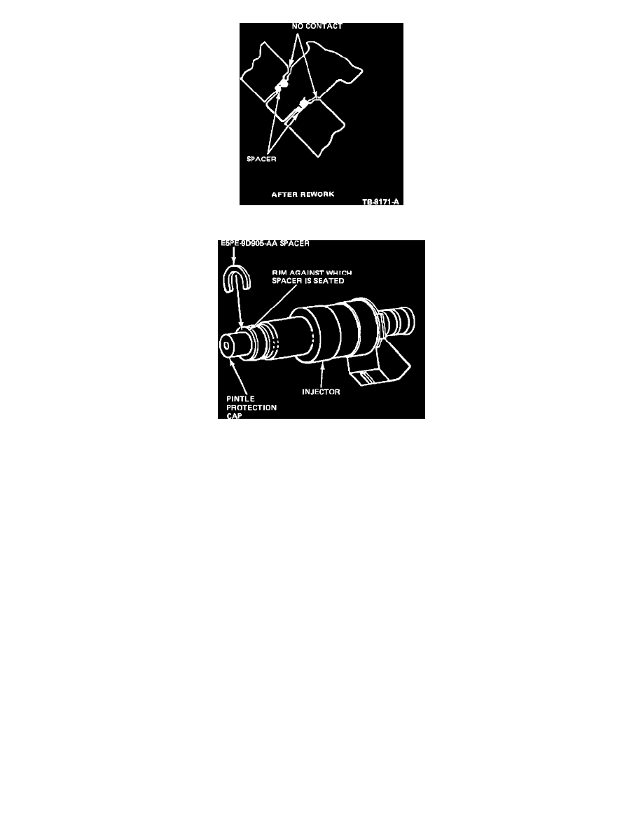
Figure 25 - Injector
Figure 26 - SPACER INSTALLATION
5.
Install injector spacer, E5PZ-9D905-A, to the pintle protection cap and seat against rim (one per injector) of all injectors in that bank. See Figure
25). The spacer is designed to function as a spring clip; visually inspect for damage after installation onto the cap.
6.
Lubricate the injector O-ring with light grade oil ESF-M6C2-A or equivalent. (Do not use silicone grease, as it might clog the injectors.)
7.
Align all four injectors in the affected bank properly against the respective cavities in the intake manifold. Apply a firm uniform pressure on
the fuel supply manifold until a distinctive snap is felt that indicates the injectors have seated in the intake manifold injector pockets. While
holding the fuel rail in the seated position, tighten the fuel supply manifold retaining bolts to 20-30 N-m (15-22 ft. lbs.)torque specification.
DO NOT check for continuity after rework (there will be continuity due to injector touching the fuel supply manifolds).
8.
Reinstall the upper intake manifold removed in Step 2 using the procedure in the Shop Manual.
Parts Affected:
E5PZ-9D905-A
Spacer (Injector)
E5TZ-9H486-A
Gasket (Manifold Upper)
9.
Following reinstallation, run engine for five minutes, for fuel leakage at all injector locations.
PART NUMBER
PART NAME
CLASS
E5PZ-9D905-A
Spacer
BG
E5TZ-9H486-A
Gasket
CG
OTHER APPLICABLE ARTICLES: None
WARRANTY STATUS: Reimbursable within the provisions of the Warranty and Policy Manual.
OPERATION: SP9905A85
TIME:
1.3 Hrs. Perform checks both sides
OPERATION: SP9905B85
TIME:
0.3 Hr. Spacer injectors install all one side
OPERATION: SP9905C85