
F 350 2WD Pickup V8-460 7.5L VIN G EFI (1997)
CAUTION: Do not damage any machined surfaces.
NOTE: A number 53 drill bit (1/16-inch) can be used as an alternative method to remove the manual lever shaft retaining pin.
9. Remove inner manual valve detent lever nut using a 21 mm box wrench while holding manual lever assembly with a crescent wrench.
10. Remove inner manual valve detent lever and parking pawl actuating rod assembly from manual control lever shaft.
11. Remove outer manual control lever shaft nut using a 15 mm open end wrench while holding manual control lever with crescent wrench.
CAUTION: After removal, discard outer manual control lever shaft nut. Do not reuse.
12. Remove manual control lever.
13. Disconnect Transmission Range (TR) sensor connector by squeezing connector tabs and pulling on connector. Check connector for terminal
condition, corrosion and contamination. Check connector seal for damage. Repair or replace as required.
14. Remove two TR sensor bolts and washers using an 8 mm socket and remove sensor.
15. Remove manual control lever shaft.
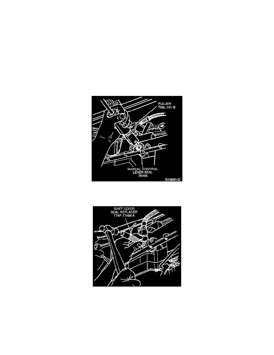
16. Remove manual control lever seal using Puller T58L-101-B.
CAUTION: Use care not to damage the manual control lever shaft bore.
INSTALLATION
1. Clean bore opening with mineral spirits. Install manual control lever seal using Shift Lever Seal Replacer T74P-77498-A.
2. Install manual control lever shaft.
3. Install manual valve detent lever, parking pawl actuating rod and nut.
NOTE: Inner manual valve detent lever must be seated on flats of manual control lever shaft. Parking pawl actuating rod must be through guide
plate. Detent lever pin must be properly engaged with manual shift valve.