
F 350 2WD Super Duty V10-6.8L (2009)
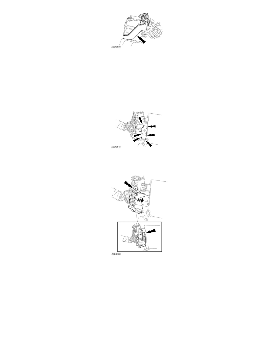
3. NOTICE: Putting the large Restraints Control Module (RCM) electrical wiring connector into the RCM on an angle can cause bad
electrical connections and damage components.
Position the large RCM electrical connector into the RCM.
-
NOTICE: Do not push the connector to where the lever pivots and seats itself. Light pressure is needed to get the connector into
position on the Restraints Control Module (RCM) before using the lever to fully seat the connector. Failure to follow this instruction
may result in component damage and/or system failure.
With the large RCM electrical connector uniformly aligned to the RCM, lightly push in until a subtle audible click is heard and slight resistance is
felt.
4. Connect the large RCM electrical connector.
-
Using the connector position assurance lever, pivot it toward the RCM, drawing the connector into the RCM.
-
Make sure the thumb tab is engaged to the retainer on the RCM and locked in place.
5. Connect the small RCM electrical connector.
6. If equipped, position back the carpet flap and tuck it back in place in the carpeting to cover the RCM.
7. If equipped, install the following front seat(s):
-
20 percent seat
-
bench seat
-
Follow the Removal and Installation procedures in Seats.
8. If equipped, connect the powerpoint electrical connector and install the floor console.
9. If equipped, install the front bucket seats.
10. Repower the SRS. Do not prove out the SRS at this time. For additional information, refer to Supplemental Restraint System (SRS) Depowering
and Repowering See: Body and Frame/Interior Moulding / Trim/Dashboard / Instrument Panel/Air Bag(s) Arming and Disarming/Service and