
F 350 4WD Pickup V8-7.3L DSL Turbo VIN F (1994)
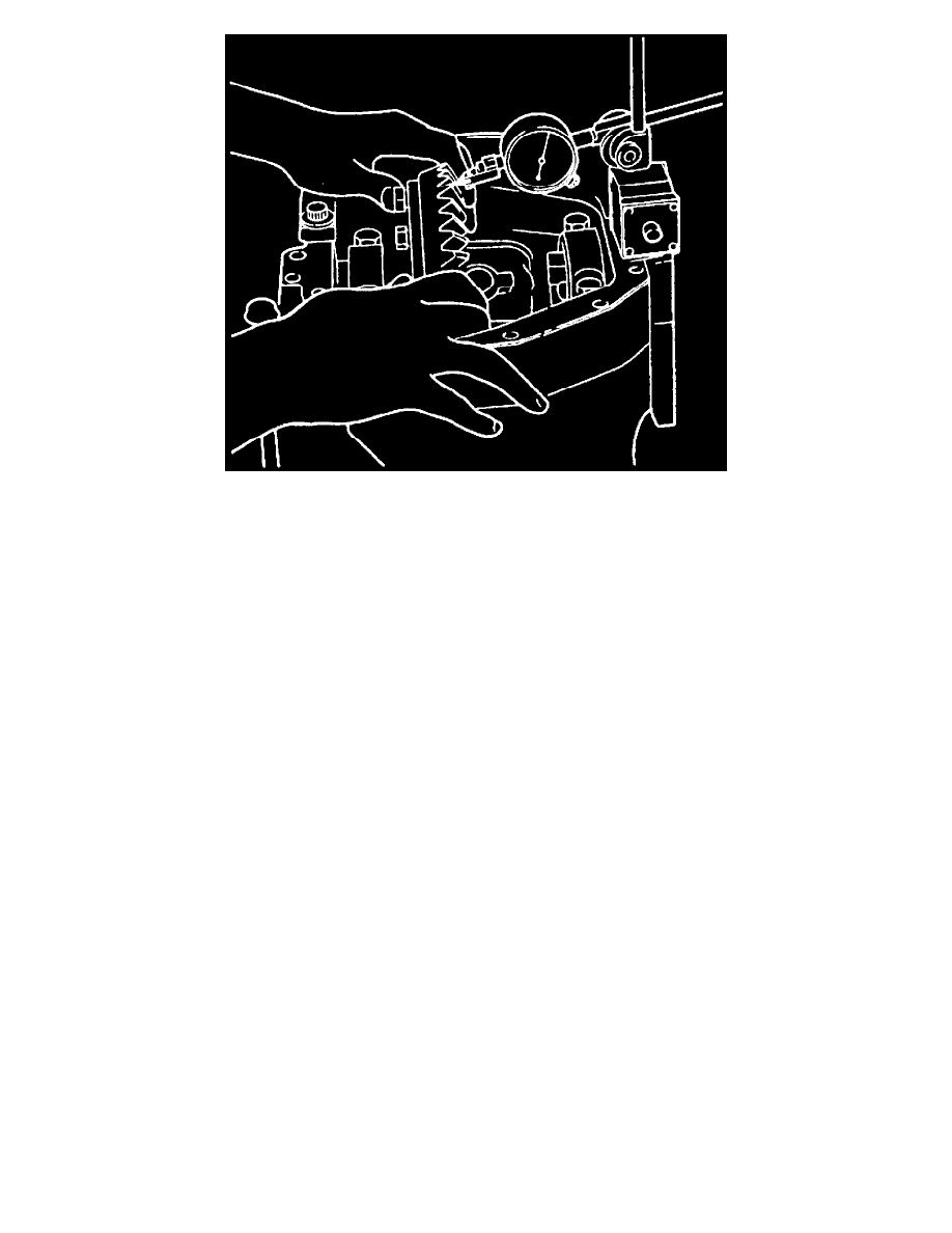
Fig. 15 Ring Gear & Pinion Backlash Inspection
17. Install dial indicator on case.
18. Check ring gear and pinion backlash at three equally spaced points on ring gear. Back lash tolerance is 0.005-0.009 inch and cannot vary more
than 0.003 inch between the three points.
19. If backlash is high, ring gear must be moved closer to pinion by moving shims to ring gear side from opposite side.
20. If backlash is low, ring gear must be moved away from pinion by moving shims from ring gear side to opposite side.
21. Install right hand slip yoke and stub shaft.
22. Apply a continuous bead of RTV silicone sealant 1/8 to 1/4 inch high and 1/4 to 1/2 inch wide on mating surfaces of carrier mounting face support
arm, then mount carrier assembly to left hand axle arm, using two guide pins. Install mounting bolts and tighten to 30-40 ft lb. Use new bolts with
encapsulated adhesive or wire brush old bolts and apply thread-locking compound part No. E0AZ-19554-A, or equivalent.
23. Allow sealant one hour cure time prior to filling carrier with proper amount of specified lubricant.
Model 60 Monobeam
TOTAL DIFFERENTIAL CASE ENDPLAY INSPECTION
1. Attach ring gear to differential case using new bolts, then tighten bolts alternately and evenly to: grade 8 bolts 100-120 ft lb, and grade 9 bolts
120-140 ft lb.
2. Clean trunnions on differential and install bearings onto differential case. Remove all burrs and nicks from hubs so bearings rotate freely.