
F 350 4WD Pickup V8-7.3L DSL Turbo VIN F (1994)
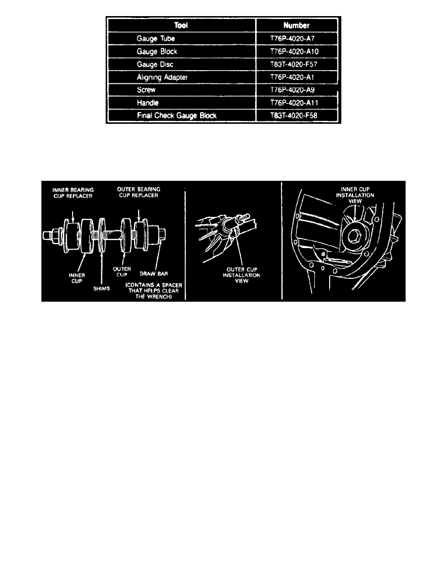
Fig. 18 Depth Gauge Tool Selection.
1. Refer to chart for correct tool usage on particular axle assemblies. If any gauge surfaces become nicked, high spots must be removed with a
medium India oilstone to ensure no erroneous readings are obtained.
2. Install oil baffle into inner bearing cup bore in carrier.
Fig. 13 Inner & Outer Pinion Cup Installation Tools
3. Install inner and outer pinion cups using suitable tools.
4. Place a new inner pinion bearing over proper aligning adapter and insert into pinion bearing retainer assembly. Place outer pinion bearing into
bearing cup in carrier and assemble handle onto screw and hand tighten. Note 3/8 inch square drive in handle to be used for obtaining proper
pinion bearing preload.
5. Center proper gauge tube into differential bearing bore, install bearing caps and tighten to 80-90 ft lb. To preload bearings, torque handle to 20-40
inch lb.
6. Using suitable feeler gauges, select thickest feeler gauge that will fit between gauge tube and gauge block. Insert feeler gauge directly along gauge
block to ensure a correct reading. Feeler gauge should fit between gauge tube and gauge block with only a slight drag.
7. After correct feeler gauge feel is obtained, thickness of feeler gauge used to obtain slight drag-type feel is the thickness of shims required,
provided new pinion gear is marked with a zero (0). If new pinion gear is marked with a plus (+) reading, the plus (+) amount stamped on pinion
gear must be subtracted from thickness dimension obtained in preceding step. If new pinion gear is marked with a minus (-) reading, the minus (-)
amount stamped on pinion gear must be added to thickness dimension obtained in preceding step. Also, you must use same new inner pinion
bearing that was used to obtain this dimension.