
F 350 4WD Pickup V8-7.3L DSL Turbo VIN F (1994)
2
Remove the differential case.
35. Install the pinion gear and the ring gear.
36. Install the front drive axle assembly.
End Play Check
DIFFERENTIAL END PLAY CHECK
1. Attach the differential ring gear to the differential case using new bolts. Tighten bolts alternately and evenly to 129-142 Nm (95-105 ft. lbs.).
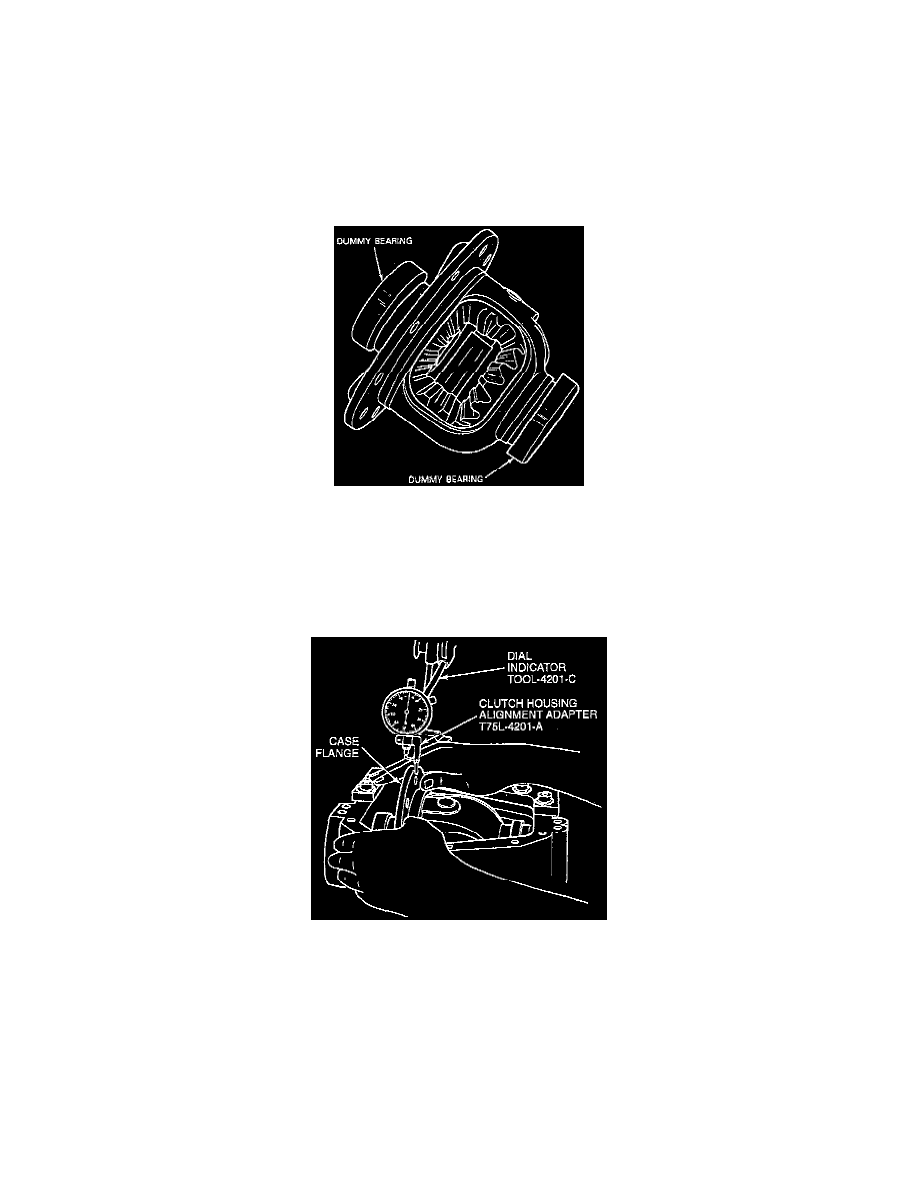
2. Clean the trunnions on the differential and install Dummy Differential Bearings D81T-4222-C or equivalent onto the differential case. Remove all
burrs and nicks from hubs so master bearings rotate.
3. Place the differential case into carrier (without pinion). The differential case should move freely in the carrier. Mount Dial Indicator/Magnetic
Base D78P-4201-B or Dial Indicator with Bracketry TOOL-4201-C or equivalent against the differential case flange as shown. Use Dial Indicator
with Clutch Housing Alignment Adapter T75L-4201-A. Locate the tip of the indicator on the flat surface of one ring gear bolt.
NOTE: Dial indicator should have a minimum travel capability of 5.08 mm (0.200 inch).
4. Force the differential case toward the dial indicator as far as possible and zero the dial indicator with force still applied.
5. Force the differential case away from the dial indicator as far as it will go. Repeat this procedure until the same reading is obtained. Record the
dial indicator reading.
NOTE: The reading obtained in this step indicates the amount of shims needed behind the differential side bearings to take up total clearance
between the differential bearing and differential case. This reading will be used under the gear tooth contact pattern check.
6. Remove the differential case from the carrier. Do not remove the dummy differential bearings at this time.