
F 450 4WD Super Duty V8-6.4L DSL Turbo (2008)
Using a new clamp, connect the EGR cooler coolant outlet hose to the horizontal EGR cooler.
^
Tighten to 4 Nm (35 lb-inch).
10. CAUTION: The coolant hose clamps used on this engine are constant tension worm gear clamps. Standard worm gear clamps cannot be
used. Failure to use the correct coolant hose clamps may result in hose joint failure.
NOTE: Install a new O-ring seal and clamp on the coolant supply tube.
NOTE: Position the flexible section of hose on the EGR cooler prior to installing the tube.
NOTE: Make sure the oil level indicator tube is positioned behind the EGR cooler coolant supply tube before installing the EGR cooler coolant
supply tube.
Position a new clamp and install the EGR cooler coolant supply tube and bolts.
^
Tighten to 13 Nm (115 lb-inch).
11. Tighten the clamp for the EGR cooler coolant supply hose.
^
Tighten to 4 Nm (35 lb-inch).
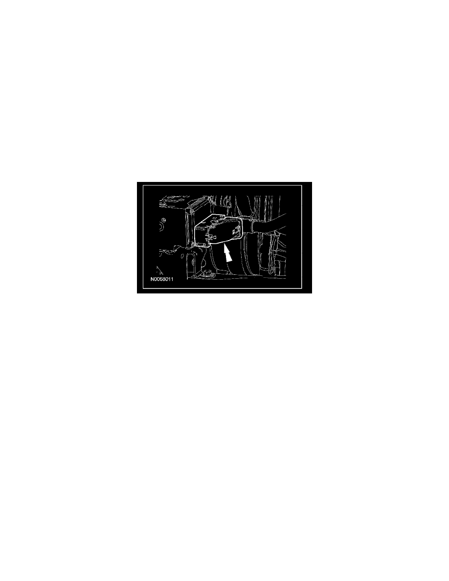
12. Connect the anti-lock module electrical connector.
13. NOTE: Install a new O-ring seal on the oil level tube prior to installing.
Position the oil level indicator tube. Install the bolt.
^
Tighten to 13 Nm (115 lb-inch).
14. Install the nut for the oil level indicator tube. Install the oil level indicator.
^
Tighten to 31 Nm (23 lb-ft).
15. Install the LH fender splash shield.
16. Install the LH front tire and wheel.
17. Install the degas bottle.
18. Install the turbocharger inlet pipe - LH.