
Festiva L4-81 1.3L SOHC EFI (1989)
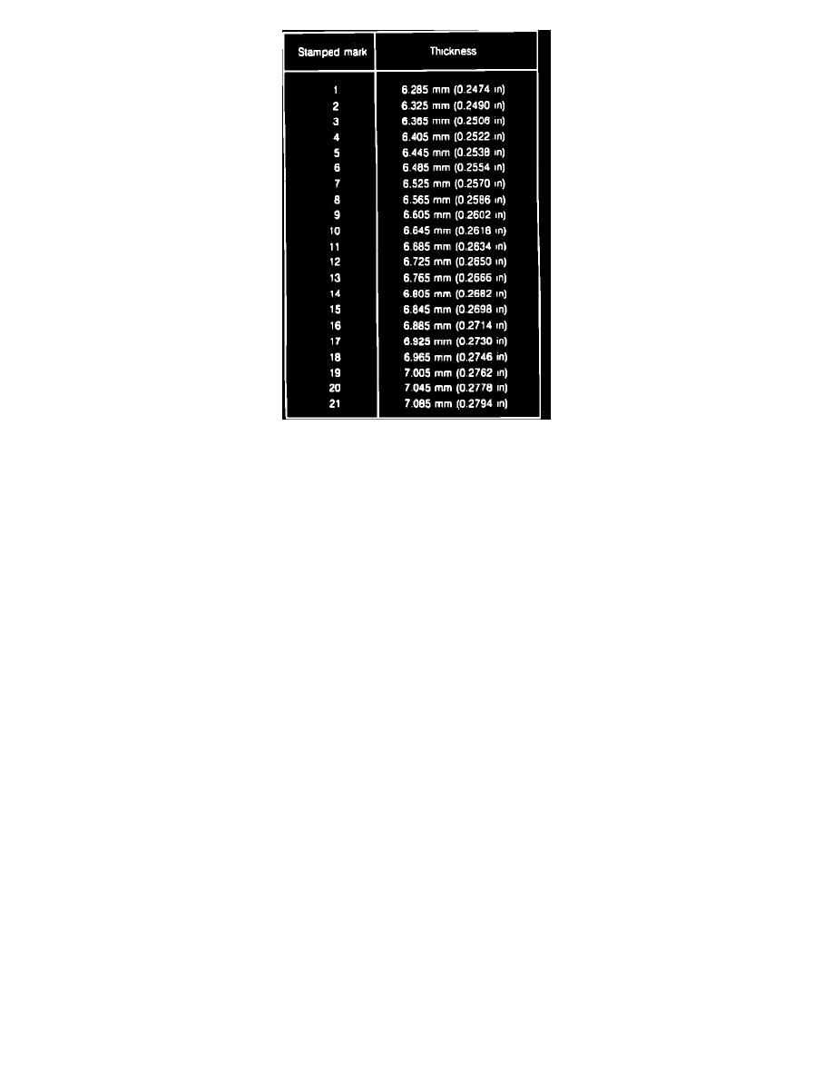
Fig. 6 Bearing Preload Spacer Identification Chart
1.
Raise and support vehicle, then remove front wheel.
2.
Unstake halfshaft attaching nut using suitable chisel, apply brakes to prevent hub assembly from turning, then remove and discard attaching nut.
3.
Remove brake hose to strut bracket retaining clip.
4.
Remove cotter pin and tie rod attaching nut, then separate tie rod from steering knuckle using suitable tool.
5.
Remove brake caliper attaching bolts, then lift caliper assembly off steering knuckle. Do not allow caliper to hang unsupported from brake
hose. Wire caliper in place as required.
6.
Remove ball joint to steering knuckle clamp bolt and nut, then pry downward on control arm and disconnect joint from knuckle.
7.
Remove steering knuckle to strut bracket attaching bolts and nuts, then slide hub/rotor assembly together with steering knuckle off end of halfshaft.
If difficulty is encountered separating hub from halfshaft, tap end of shaft with plastic mallet to facilitate removal.
8.
Separate hub/rotor assembly from steering knuckle using tool shown in Fig. 3.
9.
Remove bearing preload spacer from hub, Fig. 4. The spacer is pre-selected to yield correct bearing preload. Save spacer to use during
reassembly.
10.
Clamp hub/rotor assembly in soft jaw vise, scribe alignment marks on hub and rotor, then remove hub to rotor attaching bolts and separate rotor
from hub.
11.
Using suitable bearing remover, press hub shaft from outer bearing, then remove outer grease seal from hub.
12.
Using suitable seal remover, pry inner grease seal from steering knuckle bore, then remove inner bearing.
13.
Inspect bearings, hub, steering knuckle and dust shield for damage or excessive wear. Replace components as necessary.
14.
If original bearings and steering knuckle are being used, proceed to step 15. If bearings or steering knuckle require replacement, proceed as
follows to select proper bearing preload spacer:
a. Drive new inner and outer bearing races into steering knuckle using suitable tools.
b. Lubricate races and new bearings with engine oil, then install bearings into steering knuckle.
c. Install spacer selection tool kit T87C-1104-B, original spacer and hardware shown in Fig. 5 onto steering knuckle, then clamp steering knuckle
in soft jaw vise.
d. Tighten center bolt in increments. After bolt is tightened to specification, remove assembly from vise and rotate steering knuckle to seat
bearings.
e. Again clamp steering knuckle in vise, then measure the amount of torque necessary to start rotation of center bolt using an inch lb. torque
wrench.
f.
If torque reading is 2.2-10.4 inch lbs., spacer is correct thickness. If torque reading is less than 2.2 inch lbs., a thinner spacer must be used. If
torque reading is greater than 10.4 inch lbs., a thicker spacer must be used. Twenty one spacers of various thicknesses are available for service.
Each spacer has a number stamped on it for identification purposes, Fig. 6. Changing the spacer by one number, either up or down, will result
in a 1.7-3.5 inch lb. change in bearing preload.
15.
Pack bearings and hub with suitable high temperature grease, then install inner bearing into steering knuckle.
16.
Lubricate seal lip, then install new inner seal using suitable tool.
17.
Place original bearing preload spacer, or spacer selected in step 14, into steering knuckle.
18.
Lubricate seal lip, then install outer wheel bearing and new outer seal into knuckle.
19.
Position rotor onto hub, aligning marks made during disassembly, then install attaching bolts.